Sanyo vcb-3400p Instruction Manual Download Page 13

SPECIFICATIONS

Scanning system

:

CCIR standard (625 TV lines, 50
fields/sec.)

Interlace

:

PLL 2:1 interlace

Image device

:

1/3 inch solid state image device
CCD 

Picture elements

:

542 (H) x 582 (V)

Effective picture elements

:

512 (H) x 582 (V)

Synchronizing system

:

Internal sync/Line lock manually
switchable/External sync

Resolution

400 TV lines horizontally, 400 TV
lines vertically

Video output level

:

1.0 Vp-p/75 ohms, composite

Video S/N ratio

:

More than 50 dB

Minimum required
illumination
 (incandescent lighting)

:

Approx. 0.07 lux with a F 1.2 lens,
approx. 0.1 lux with a F 1.4 lens

Backlight compensation

:

Manual ON/OFF switching, zone light
measuring system
(active when using an auto-iris lens)

Electronic iris function

:

Manual ON/OFF switching

AGC

:

Manual ON/OFF switching

Flange-back

:

12.5 mm 

±

 0.8 mm

Gain control

:

Manual ON/OFF switching

Gamma correction

:

γ

 = 0.45

Lens mount

:

CS mount (or C mount with the
supplied adaptor)

Environmental conditions

:

Temperature: –10˚C ~ +50˚C
Humidity: less than 90% (no
condensation)

Power supply

:

220 – 230 V AC 

±

 10 %, 50 Hz

Power consumption

:

3.1 W (with auto iris lens)
2.7 W (without auto iris lens)

Weight

:

Approx. 620 g (without lens)
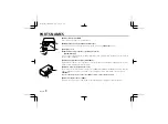
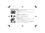
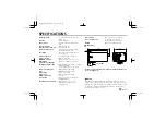
Dimensions

Features and specifications are subject to change without prior
notice or obligations.

SERVICE

This camera is a precision instruments and if treated with care, will
provide years of satisfactory performance. However, in the event of a
problem, the owner is advised not to attempt to make repairs or open
the cabinet. Servicing should always be referred to your dealer or
Sanyo Authorized Service Centre.

12

22

11

1.3

136
128

1/4”–20 UNC

VIDEO OUT

VS IN

POWER

LINE PHASE

67

54

28

L73T5/XE (VCB-3400P)  GB  2000, 3, 14

12 

English

Summary of Contents for vcb-3400p

Page 1: ...sure to keep it handy for later reference Über diese Bedienungsanleitung Lesen Sie bitte vor der Montage und dem Inbetriebnehmen der Kamera zuerst diese Bedienungsanleitung sorgfältig durch und bewahren Sie sie zum späteren Nachschlagen auf A propos de ce manuel Avant d installer et d utiliser la caméra veuillez lire ce manuel attentivement Gardez le à portée de main pour toute référence ultérieur...

Page 2: ... 2 3 4 FEATURES Built in interline transfer method 1 3 CCD approx 320 000 picture elements Low smear anti blooming low lag no burning and no geometric distortion using the CCD solid state image device 100 solid state components giving excellent immunity to shock and vibration Not subject to interference from magnetic or electrostatic fields High sensitivity minimum required illumination of 0 07 lu...

Page 3: ...peakers the magnetic field they generate will distort the image Protect from humidity and dust To prevent damages to the camera do not install it where there is greasy smoke or steam where the dampness may get too high or where there is a lot of dust Protect from high temperatures Do not install close to stoves or other heat generating devices such as spotlights etc or where it could be subject to...

Page 4: ...hen using two cameras or more the image on the monitor may roll vertically when switching sources This rolling can be minimized by turning this volume 6 Camera setup section under the cover These settings are for when using a 1 3 inch CS mount DC without EE internal amplifier type lens However if due to installation conditions or environment the settings may need to be modified for best results se...

Page 5: ...cket The bracket can be fixed at the top or bottom of the camera When fixing the bracket be sure to use the longer screws and install the shorter screws on the opposite side to seal the openings 1 Shorter screws M3 x 4 2 Longer screws M3 x 6 3 Camera mounting screw hole 1 4 20 UNC CAUTION When installing the camera bracket select a location that can support the total weight of the camera and acces...

Page 6: ...ailable on the lens for iris adjustments Set the A I LENS switch to the VIDEO position Compatible auto iris lenses 1 3 inch Sanyo DC type lens VIDEO type lens VCL CS8LY Standard angle f 8 mm Standard angle f 9 mm VCL CS4LY Wide angle f 4 mm Telephoto angle f 12 mm VCL CS2LY Ultra wide angle f 2 8 mm More telephoto angle f 16 mm If using a VIDEO type auto iris lens Set the ALC and LEVEL controls on...

Page 7: ...t then carefully align the lens mount with the camera opening and turn the lens slowly to install it 3 Connect the lens plug to the lens iris output connector LENS on the side of the camera When using lenses from other makers the plug shape may not correspond to the terminal on the camera In such a case remove the original plug and using a soldering iron connect the supplied lens iris plug accordi...

Page 8: ...the pick up surface is not correctly positioned with relation to the lens focal point the picture will be out of focus in particular when using auto iris power zoom lenses sold separately If that is the case adjust the flange back position as described below 1 Using a screwdriver loosen the FLANGE BACK LOCK screw M2 2 Set the zoom lens to the maximum telephoto position set the focus using the focu...

Page 9: ...other devices connected 3 Insert the plug of this power cord into a wall outlet The POWER indicator A will light Adjust the picture on the monitor using the Brightness and Contrast controls Coaxial cable type and maximum length Cable type RG 59U 3C 2V 250 m maximum Cable type RG 6U 5C 2V 500 m maximum Cable type RG 11U 7C 2V 600 m maximum CAUTION The RG 59U type cable should not be run through ele...

Page 10: ...or normal indoor use When the EI switch is set to the ON position do not use an auto iris lens If used under fluorescent light the image may flicker In such a case change to incandescent lighting or set the EI switch to the OFF position and use an auto iris lens When shooting bright subjects pay attention to the light angle in order to avoid or minimize the smear phenomenon effect When using an au...

Page 11: ...sed horizontally For example this setting can be used if the camera is installed at the back of a truck or bus and looking towards the back the image will be as seen in the mirrors Backlight compensation setting Use an auto iris lens and set the BLC switch to the ON position to engage the backlight compensation function If using a VIDEO type auto iris lens The ALC volume on the lens should be turn...

Page 12: ...correctly If it still does not perform correctly please consult your dealer or a Sanyo Authorized Service Centre No picture on the monitor screen Is the power turned on to all connected devices Is the voltage correct Are all the signal connecting cables correctly connected Is the lighting sufficient Has the lens cap been removed Is the lens type DC or VIDEO correctly selected Depending on the type...

Page 13: ...GC Manual ON OFF switching Flange back 12 5 mm 0 8 mm Gain control Manual ON OFF switching Gamma correction γ 0 45 Lens mount CS mount or C mount with the supplied adaptor Environmental conditions Temperature 10 C 50 C Humidity less than 90 no condensation Power supply 220 230 V AC 10 50 Hz Power consumption 3 1 W with auto iris lens 2 7 W without auto iris lens Weight Approx 620 g without lens Di...

Page 14: ...1AC6P1P2279 L73T5 XE 0300KP NI SANYO Electric Co Ltd Printed in Japan L73T5 XE VCB 3400P GB 2000 3 14 ...

Reviews: