


1
Name and Function of Each Component ..................................................................... 2
Installation .................................................................................................................... 3
Connections ................................................................................................................. 5
Control/Address Settings ............................................................................................. 9
Address Settings Table............................................................................................... 10
Network Settings ........................................................................................................ 11
Specifications ............................................................................................................. 12
Copyright Notice ........................................................................................................ 14
Check your operating environment.
To operate the camera via network operation, you must meet the following operating requirements.
PC
•
: IBM PC/AT compatible
Operating system
•
: Windows XP Professional/Windows Vista
CPU
•
: Core2Duo E6700 2.66 GHz or higher
Memory
•
: Windows XP: 1GB or more
Windows Vista: 2GB or more
Network interface
•
: 10Base-T/100Base-TX (RJ-45 connector)
Display card
•
: 1920×1200 pixels or higher
Graphics chip
•
: ATI RADEON HD2600 series or higher
nVIDIA GeForce 8600 series or higher
nVIDIA Quadro FX550 series or higher
Web browser
•
: Internet Explorer Ver. 6.0 SP2 or higher,
or Internet Explorer Ver. 7.0
■
You can automatically set up the IP address of the camera.
This software application is useful when two or more cameras are connected to the network.
Download “Auto IP Setup” software application from the supplied CD-ROM.
■
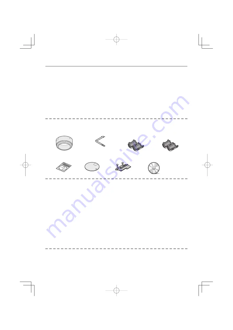
Contents
Accessories
Camera Unit
①
Surface cover
②
Drop-prevention cable
③
Clamping core
(VCC-MCH5600)
× 4
(VCC-MCH5600P)
× 5
Power unit
①
Pattern sheet
②
Dust sheet
③
Interface board
④
CD-ROM
■
•
•
L5DD2̲VA-94S̲MCH5600P̲GB.indd Sec1:1
L5DD2̲VA-94S̲MCH5600P̲GB.indd Sec1:1
2009/10/23 12:06:22
2009/10/23 12:06:22


