background image

23

Turning On the Projector

Connect the projector’s AC power cord into an AC 

outlet and turn on the MAIN ON/OFF Switch. The 

LAMP indicator lights red and the READY indicator 

lights green.

Press the ON/STAND-BY button on the side control 

or on the remote control. The LAMP indicator 

dims red and the cooling fans start to operate. The 

preparation display appears on the screen and the 

countdown starts. 

2

3

1

16

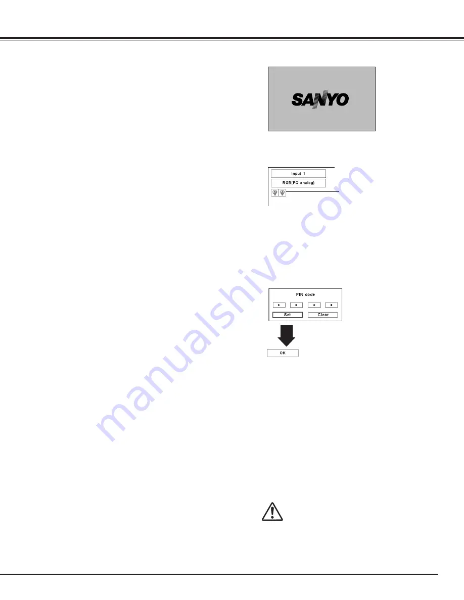
The preparation display will disappear after 20 

seconds.

4

After the countdown, the input source that was 

selected the last time and the Lamp mode icon (see 

page 60) appear on the screen.

If the projector is locked with a PIN code, PIN code 

Input Dialog Box will appear. Enter the PIN code as 

instructed below.

Selected Input Source and Lamp control

Complete peripheral connections (with a computer, 

VCR, etc.) before turning on the projector. 

what is PIN code?

PIN (Personal Identification Number) code is a security 

code that allows the person who knows it to operate the 

projector. Setting a PIN code prevents unauthorized use 

of the projector. 

A PIN code consists of a four-digit number. Refer to the 

PIN code lock function in the Setting Menu on page 53-

54 for locking operation of the projector with your PIN 

code.

PIN code Input Dialog Box

Enter a PIN code

CAUTION ON HANDLING PIN CODE

If you forget your PIN code, the projector 

can no longer be started. Take special care 

in setting a new PIN code; write down the 

number in a column on page 80 of this 

manual and keep it on hand. Should the 

PIN code be missing or forgotten, consult 

your dealer or service center.

After the OK icon 

disappears, you can 

operate the projector. 

Lamp mode

See page 60 for the Lamp mode status

Note:

• The Lamp replacement icon and the Filter warning 

icon may appear on the screen depending on the 

usage state of the projector.

Use the Point 

ed

 buttons on the side control or on the 

remote control to enter a number. Press the Point 

8


button to fix the number and move the red frame pointer 

to the next box. The number changes to “

.” Repeat 

this step to complete entering a four-digit number. After 

entering the four-digit number, move the pointer to “Set.” 

Press the SELECT button so that you can start to operate 

the projector.

If you fixed an incorrect number, use the Point 

7

 button 

to move the pointer to the number you want to correct, 

and then enter the correct number.

If you entered an incorrect PIN code, “PIN code” and the 

number (

✳✳✳✳

) will turn red for a moment. Enter the 

correct PIN code all over again.

Note:

• When the Logo select function is set to “Off,” the 

logo will not be shown on the screen (p.49).

• When the “Countdown off” or “Off” is selected 

in the Display function, the countdown will not be 
shown on the screen (p.48).

• During the countdown period, all operations are 

invalid.

• If the PIN code number is not entered within three 

minutes after the PIN code dialog box appeared, 
the projector will be turned off automatically.

• The “1234” is set as the initial PIN code at the 

factory.

Basic Operation

Summary of Contents for PLC-XF1000

Page 1: ...Multimedia Projector MODEL PLC XF1000 Owner s Manual Projection lens is optional ...

Page 2: ...ular omnidirectional projection variety of lens options etc Motor driven Lens Shift Shutter Function The projector is equipped with the shutter that provides complete blackness for a while the projected image is not needed with keeping the projector on The Shutter management function allows you to set the timer It prevents leaving the projector on with the shutter closed for a long time p 55 Multi...

Page 3: ...ning On the Projector 23 Turning Off the Projector 24 How to Operate the On Screen Menu 25 Menu Bar 26 Operating with Projector Control 27 Operating with Remote Control 29 Input Selection 31 Input 31 Computer Input Source Selection 32 Video Input Source Selection 33 Computer Input 34 Computer System Selection 34 Auto PC Adjustment 35 Manual PC Adjustment 36 Image Level Selection 38 Screen Size Adj...

Page 4: ...S APPARATUS MUST BE EARTHED l TO REDUCETHE RISK OF FIRE OR ELECTRIC SHOCK DO NOT EXPOSETHIS APPLIANCETO RAIN OR MOISTURE This projector produces intense light from the projection lens Do not stare directly into the lens otherwise eye damage could result Be especially careful that children do not stare directly into the beam Install the projector in a proper position Otherwise it may result in a fi...

Page 5: ...rt out parts that could result in a fire or electric shock Never spill liquid of any kind on the projector Do not install the projector near the ventilation duct of air conditioning equipment This projector should be operated only from the type of power source indicated on the marking label If you are not sure of the type of power supplied consult your authorized dealer or local power company Do n...

Page 6: ...nt heat The cooling fans and air vents are provided to dissipate the heat by drawing air into the housing and the filter is located in the intake vents to prevent dust from getting inside of the projector In order to care for the projector appropriately regular cleaning is required Remove any dirt or dust that has accumulated on the projector If the projector reaches a time set in the timer settin...

Page 7: ...ing mount kit designed for this projector When not mounted properly the projector may fall causing hazards or injury For details consult your dealer The warranty on this projector does not cover any damage caused by use of any non recommended ceiling mount kit or installation of the ceiling mount kit in an improper location CAUTION ON CEILING MOUNTING 10 10 Do not put the projector on either side ...

Page 8: ...tor by courier or any other transport service consult your dealer Do not put the projector in a case before it is cooled enough Do not transport the projector with a replacement lens installed Safety Instructions Retract the adjustable feet to prevent damage to lens and cabinet For safety holding the projector on both sides by 2 or more people is recommended to move the projector because the proje...

Page 9: ...h this projector meets the requirement for use in the country you purchased it AC Power Cord for the United States and Canada AC Power Cord used in the United States and Canada is listed by the Underwriters Laboratories UL and certified by the Canadian Standard Association CSA AC Power Cord has a grounding type AC line plug This is a safety feature to be sure that the plug will fit into the power ...

Page 10: ... side 0 Infrared Remote Receiver Rear 1 Exhaust Vent t Adjustable Feet y Terminals and Connectors u Handle i Side Control o Lamp Cover 1 3 Part Names and Functions 0 4 5 t t t 1 Kensington Security Slot This slot is for a Kensington lock used to deter theft of the projector Kensington is a registered trademark of ACCO Brands Corporation 2 Main On Off Switch 3 Power Cord Connector 4 Air Intake Vent...

Page 11: ... IN of another projector to this terminal u 5 BNC INPUT JACKS Connect the component or composite video output signal from video equipment to VIDEO Y Pb Cb and Pr Cr jacks or connect the computer output signal 5 BNC Type Green Blue Red Horiz Sync and Vert Sync to G B R H V and V jacks pp 20 21 RESET button A built in micro processor which controls this unit may occasionally malfunction and need to ...

Page 12: ...ust the value in the On Screen MENU p 25 Pan the image in DIGITAL ZOOM mode p 40 Side Control and Indicators u LENS SHIFT button Select the LENS SHIFT function p 27 0 SELECT button Used to execute the selected item p 25 It is also used to expand or compress the image in DIGITAL ZOOM mode p 40 e MENU button Open or close the On Screen MENU pp 25 26 Part Names and Functions SIDE CONTROLS INDICATORS ...

Page 13: ...eady to be turned on And it flashes green in Power Management mode pp 52 72 74 Part Names and Functions r WARNING FILTER indicator Blink slow when the filter is being scrolled pp 57 72 Blink fast when the filter scroll is not working properly or the filter cartridge is not installed pp 57 74 Light orange when the clogging of the filter is detected or the filter counter reaches a time set in the ti...

Page 14: ...ts optimum setting pp 29 35 4 SHUTTER button Close the built in shutter for light blocking pp 27 30 5 SELECT button Execute the selected item p 25 Expand or compress the image in the DIGITAL ZOOM mode p 40 1 Wired Remote Jack Connect the remote control cable not supplied to this jack when using as a wired remote control 0 IMAGE SEL button Select the image level pp 30 38 42 8 INPUT 1 2 3 4 buttons ...

Page 15: ...instructions Point the remote control toward the projector to Infrared Remote Receivers when pressing the buttons Maximum operating range for the remote control is about 16 4 5 m and 60 degrees in front and rear of the projector Infrared Remote Receivers are provided both in front and back of the projector You can conveniently use both of the receivers pp 10 52 16 4 5 m Remote Control Receivers an...

Page 16: ...te control in the Setting Menu on page 52 1 2 Remote Control Code Part Names and Functions Flip the Reset Switch to Use position in the compartment lid on the back of the remote control While holding down the MENU button press and release the IMAGE ADJ button the number of corresponding times you would like to set the number of the remote control code for the projector Remote Control Code Number o...

Page 17: ...al parts Installing the Strap for safety Secure the lens mount cover and the projector with the strap supplied to prevent the lens mount cover from falling down Fig 1 Screw A Fig 3 Label Dot on the cabinet Dot on the lens mount cover Strap Remove the screw A See Fig 1 Turn the lens mount cover counter clockwise and take it off by pulling forward See Fig 1 1 2 Fit the raised dot of the lens mount c...

Page 18: ...lens is shifted to rightmost The display position can be shifted to the right in up to 10 width of the display The projection angle is adjustable up to 2 8 degrees upward and downward respectively by rotating front and back feet To raise the projector rotate the feet clockwise To lower the projector or to retract the adjustable feet rotate the feet counterclockwise To correct keystone distortion p...

Page 19: ...e board Insert a new interface board along Guide to fit Socket to inside Plug 3 4 INPUT OUTPUT TERMINALS Guide Socket Plug Figure shows Dual SDI terminal DVI D sub 15 Terminal 5 BNC VideoTerminal 2 TERMINAL SLOTS Factory set NOTES ON ORDERING OR USING OPTIONAL INTERFACE BOARD When ordering or using Optional Interface Board contact your sales dealer When contacting the sales dealer tell the Option ...

Page 20: ...put DVI Cable BNC Cable Monitor Output Unplug the power cords of both the projector and external equipment from the AC outlet before connecting cables Cables used for connection VGA Cable D sub 15 pin DVI Cable BNC Cable BNC x 5 One cable is supplied Other cables are not supplied with this projector G V H HV R B DIGITAL ANALOG ...

Page 21: ...nt Video Output BNC Cable Digital Output HDCP compatible DVI Cable SCART VGA Cable DIGITAL Unplug the power cords of both the projector and external equipment from the AC outlet before connecting cables S Video Output S VIDEO Cables used for connection Video Cable BNC x 3 BNC x 1 SCART VGA Cable DVI Cable S Video Cable Cables are not supplied with the projector Composite Video Output S Video Cable...

Page 22: ...ages of 100 120 or 200 240 V AC It is designed to work with single phase power systems having a grounded neutral conductor To reduce the risk of electrical shock do not plug into any other type of power system If you are not sure of the type of power being supplied consult your authorized dealer or service center Connect the projector with all peripheral equipment before turning on the projector C...

Page 23: ...setting a new PIN code write down the number in a column on page 80 of this manual and keep it on hand Should the PIN code be missing or forgotten consult your dealer or service center After the OK icon disappears you can operate the projector Lamp mode See page 60 for the Lamp mode status Note The Lamp replacement icon and the Filter warning icon may appear on the screen depending on the usage st...

Page 24: ...en you can turn on the projector To turn off the MAIN ON OFF Switch wait until the projector is completely cooled down Power off disappears after 4 seconds Note When the On start function is set to On the projector will be turned on automatically by connecting the AC power cord to an AC outlet p 53 The running speed of cooling fans is changed according to the temperature inside the projector Do no...

Page 25: ... data Use the Point 7 8 buttons to adjust the values To close the On Screen Menu press the MENU button again Press the MENU button on the side control or the remote control to display the On Screen Menu Note The selected item is not active until the SELECT button is pressed 1 2 3 Remote Control POINT buttons SELECT button MENU button Basic Operation Pointer red frame Pointer red frame Press the Po...

Page 26: ...t Brightness Color Tint Color management Auto picture control Advanced color Color temp White balance R G B Offset R G B Sharpness Gamma Noise reduction Progressive Reset Store pp 45 47 Used to select the system of selected video source p 41 For detailed functions of each menu see Menu Tree on pages 69 71 Used to set the projector s operating configurations pp 48 56 Used to adjust the size of the ...

Page 27: ...us POINT buttons Basic Operation ZOOM button FOCUS button LENS SHIFT button Operate the Auto PC Adj function The computer screen adjustment can be done easily by pressing this button See page 35 for details Auto PC Adjustment AUTO PC ADJ button INFORMATION button Shutter Function Shutter function allows you to completely block out light to the screen Press the SHUTTER button to close the shutter i...

Page 28: ...the projector Press the INFORMATION button to display the information window on the screen To hide the information window press the INFORMATION button again or Point 7 8 buttons The information window can also be selected from the menu Information Menu Information Menu The H and V sync freq values described in this figure may be different from the actual values ...

Page 29: ...n on the remote control to select the desired screen size The selected screen size mode appears on the screen for 4 seconds See pages 39 to 40 and 43 to 44 for details Press and hold the SCREEN button for more than 5 seconds to return all the screen size adjustment setting to the factory default setting SCREEN button Press the ZOOM buttons on the remote control to zoom in and out the image See pag...

Page 30: ...button again P TIMER button P Timer display Remote Control P TIMER button SHUTTER button Note See the previous page for the description of other buttons IMAGE ADJ button Press the KEYSTONE button on the remote control The Keystone appears on the screen Use the Point ed7 8 buttons to correct keystone distortion The keystone adjustment can be stored pp 40 44 Basic Operation KEYSTONE button IMAGE SEL...

Page 31: ...ontrol Operation Side Control INPUT button Press the INPUT button on the side control It switches to INPUT 1 INPUT 2 INPUT 3 and INPUT 4 as you press the INPUT button Before using the INPUT button on the side control you must select a correct input source by On Screen Menu and the latest input source will be displayed Side Control Operation Side Control button operation Input Selection INPUT butto...

Page 32: ...red arrow to Input 1 and press the SELECT button Computer Input Source Selection When Selecting the INPUT 1 with DVI D sub 15 terminals When your computer is connected to the INPUT 1 ANALOG terminal select RGB PC analog When your computer is connected to INPUT 1 DIGITAL terminal select RGB PC digital RGB PC digital When Selecting the INPUT 2 with 5 BNC Video S Video terminals INPUT MENU INPUT Menu...

Page 33: ...e pointer red arrow to RGB Scart or RGB AV HDCP and press the SELECT button Source Select Menu Input Menu icon Move the pointer red arrow to Input 1 and press the SELECT button RGB AV HDCP RGB Scart When scart video equipment is connected to the INPUT 1 ANALOG terminal select RGB Scart If the HDCP compatible signal source is connected to the INPUT 1 DIGITAL terminal select RGB AV HDCP INPUT MENU W...

Page 34: ...ection between your computer and the projector See Troubleshooting on page 66 Auto PC System Menu icon Selected system is displayed PC SYSTEM MENU Selecting Computer System Manually Press the MENU button to display the On Screen Menu Use the Point 7 8 buttons to move the red frame pointer to the PC System Menu icon Use the Point ed buttons to move the red arrow pointer to the desired system and th...

Page 35: ...otal dots Horizontal and Vertical position of certain computers cannot be fully adjusted with the Auto PC Adjustment function When the image is not provided properly with this operation manual adjustments are required pp 36 37 Auto PC Adjustment cannot be operated in Digital Signal Input on the DVI terminal and 480p 575p 480i 575i 720p 1035i or 1080i is selected on the PC SYSTEM Menu Depending on ...

Page 36: ...c Use the Point 7 8 buttons to adjust the number of total dots in one horizontal period to match your PC image Total dots Use the Point 7 8 buttons to adjust the horizontal picture position Position H Use the Point 7 8 buttons to adjust the vertical picture position Position V Press the SELECT button to show H sync freq and V sync freq of the connected computer Current mode Use the Point 7 8 butto...

Page 37: ... return to their previous figures To store the adjusted data To clear the adjusted data To clear the adjusted data select Mode free and then press the SELECT button Move the red arrow pointer to the Mode that you want to clear and then press the SELECT button Reset Mode free Store Quit This Mode has stored parameters Vacant Values of Total dots Position H Position V Display area H and Display area...

Page 38: ...picture level preset on the projector Standard Picture level with improved halftone for graphics Real User preset picture adjustment in the Image Adjust Menu p 47 IMAGE 1 10 Image Level Selection Menu Operation Image Select Menu icon Move the red frame pointer to the desired level and press the SELECT button Computer Input Press the IMAGE SEL button on the remote control to select the desired imag...

Page 39: ...ideo aspect ratio 16 9 by expanding the image width uniformly This function can be used to provide the squeezed video signal at 16 9 Full screen Provide the full screen image Screen Menu icon Move the red frame pointer to the desired function and press the SELECT button Scale H V Adjust the Horizontal Vertical screen scale H V When set to On the aspect ratio is fixed The Scale V appears dimmed and...

Page 40: ...the keystone correction when the Main On Off Switch is pressed to Off or the AC power cord is unplugged To correct keystone distortion press the Select button The Keystone dialog box appears Use the Point ed7 8 buttons to correct keystone distortion p 30 Ceiling Rear Ceiling When this function is set to On the picture is top bottom and left right reversed This function is used to project the image...

Page 41: ... and adjusts itself to optimize its performance When the Video System is 1035i or 1080i select the system manually If the projector cannot reproduce proper video image select a specific component video signal format from among 480i 575i 480p 575p 720p 1035i and 1080i Auto COMPONENT VIDEO SIGNAL FORMAT Video Jack or S Video Jack Y Pb Cb Pr Cr Jacks The projector automatically detects an incoming vi...

Page 42: ...mage Level Selection Move the red frame pointer to the desired level and press the SELECT button Image Select Menu icon Normal picture level preset on the projector Standard Picture level adjusted with fine tone Cinema User preset picture adjustment in the Image Adjust Menu p 47 IMAGE 1 10 Menu Operation Video Input Press the IMAGE SEL button on the remote control to select the desired image level...

Page 43: ... modified based on the aspect ratio Position H V Adjust the Horizontal Vertical screen position Common Save the adjusted scale to all the inputs Press the SELECT button at Common to display a confirmation box To save the scale press the SELECT button at Yes When Custom is selected the saved scale is used Reset Reset the all adjusted values Press the SELECT button at Reset to display a confirmation...

Page 44: ...ialog box appears Use the Point ed7 8 buttons to correct keystone distortion p 30 Ceiling Rear Ceiling When this function is set to On the picture is top bottom and left right reversed This function is used to project the image from a ceiling mounted projector Rear When this function is set to On the picture is left right reversed This function is used to project the image from the rear of the scr...

Page 45: ...required You can store up to eight 8 color management data 1 Use the Point ed buttons to move the red frame pointer to Color Management and then press the SELECT button The projected image freezes and the COLOR MANAGEMENT POINTER appears Use the Point ed7 8 buttons to move the pointer to the spot where you want to adjust the color and then press the SELECT button The COLOR SELECTION window appears...

Page 46: ...color in that line This option is not available if the check mark is cleared Select the DEL box if you want to delete the adjusted data Press the SELECT button and a confirmation box appears and then select Yes Delete all the data in the list Press the SELECT button and a confirmation box appears and then select Yes The same function as stated above Level and phase adjustment palette Gamma adjustm...

Page 47: ...e Point 8 button to deepen red green blue tone of the black level of an image from 0 to 63 Offset Red Green Blue Exit the Image Adjust Menu To store the adjusted data move the red frame pointer to the Store icon and press the SELECT button The Image Level Menu appears Move the red arrow pointer to any of the Image 1 to 10 in which you want to set and press the SELECT button A confirmation box appe...

Page 48: ...This function is used to adjust the On Screen Menu display position Press the SELECT button and the adjustment screen appears arrows appear Use the Point ed7 8 buttons to adjust the position After making the adjustment press the SELECT button to return to the Menu screen Position This function allows you to adjust the position of the On Screen Display and the value adjustment bar in the Picture Im...

Page 49: ...s not captured This function decides on the starting up display from among the following options User Show the image you captured Default Show the factory set logo Off Show the countdown display only Capture Logo select Logo Note When On is selected in the Logo PIN code lock function Logo select and Capture functions cannot be selected This function enables you to capture an image being projected ...

Page 50: ...setting refer to PIN code lock on pages 53 54 Logo PIN Code Lock Enter a Logo PIN code Use the Point 7 8 buttons to switch On Off and then press the Point d button to move the pointer to Quit Press the SELECT button to close the dialog box Change the Logo PIN code lock setting caution whenyou have changedTHE LOGO PIn code write downthe new pin code in column ofthe LOGO pin code no memo on page 80 ...

Page 51: ...er When the Lamp Mode is switched from 1 lamp mode to 2 lamps mode the image becomes brighter gradually Note When neither of the two lamps is lighted the projector will shutdown automatically When either of the two lamps does not light up the LAMP 1 2 REPLACE indicator blinks orange and the projector will light the other automatically After changing the Lamp Mode it cannot be switched again for 90...

Page 52: ...closed while the Power management function is working the Power management function is released Setting RC sensor Select a location of the infrared remote receiver of the remote control See Remote Control Receivers and Operating Range on page 15 for details Both Activate both the front and back receiver Front Activate only the front receiver Back Activate only the back receiver Remote control Remo...

Page 53: ...ord is unplugged as long as the AC power cord is connected and the Main On Off Switch is pressed to ON the projector can be operated without a PIN code Whenever you change the PIN code lock setting or the PIN code the four digit number you are required to enter the PIN code 1234 is set as the initial PIN code at the factory If you want to change the PIN code lock setting press the SELECT button an...

Page 54: ...g box appears Enter a PIN code Setting Use the Point 7 8 buttons to adjust the Projector ID Projector ID 1 999 Factory default setting Projector ID 1 This feature allows users to set serial communication configuration Projector ID when several projectors are connected via the RS 232C terminal serial port of the projector Projector ID Use the Point ed buttons on the side control or on the remote co...

Page 55: ...dicator is blinking blue during this cooling off period When the lamp has been fully cooled down the READY indicator turns green lighting and the SHUTTER indicator keeps blinking Should the ON STAND BY button be pressed in this condition the projection lamp will be turned on and the SHUTTER indicator turns off Lamp counter This function is used to reset the lamp counter When the lamp life reaches ...

Page 56: ...ange indicating that the filter cartridge replacement is necessary To set a timer press the SELECT button on Used time option Move the red arrow pointer to the timer setting option and use the Point 7 8 buttons to select from Off 400H 700H 1000H depending on the use environment When replacing the Filter cartridge reset the Filter counter and the Scroll counter p 59 Filter counter Filter replacemen...

Page 57: ... is not installed properly or the filter scroll is not working properly p 74 Fig 1 Filter replacement icon Fig 4 Filter cartridge replacement icon Fig 3 Last scroll icon Note Fig 1 Fig 2 Fig 3 or Fig 4 will not appear when the Display function is set to Off p 48 or during Freeze p 29 The filter cannot be rewound The filter can be scrolled 9 times since the filter cartridge has 10 scrolls The filte...

Page 58: ...ll out the filter cartridge by holding the finger grip RECOMMENDATION We recommend avoiding dusty smoky environments when operating the projector Usage in these environments may cause a poor image quality When using the projector under dusty or smoky conditions dust may accumulate on a lens liquid crystal panels or optical elements inside the projector Such condition may degrade the quality of the...

Page 59: ...ing Menu icon Use the Point ed buttons to move the red frame pointer to Filter counter and then press the SELECT button A dialog box appears showing the Used time option and the Scrolls remaining option Use the Point ed buttons to select Used time 1 2 Resetting the Filter Counter Filter counter Select Reset and the Filter counter Reset appears Select Yes then another confirmation box appears Selec...

Page 60: ...its end When the image becomes darker or the color becomes unnatural replace lamp LAMP 1 2 REPLACE indicator lights orange LAMP 1 2 REPLACE indicator flashes orange Projection lamp is defective or fails to be turned on Restart the projector on and make sure lamp is on If this mark still appears replace lamp corresponding with number marked X LAMP STATUS DISPLAY Lamp Mode Changeover The Lamp Manage...

Page 61: ...ng LAMP 1 LAMP 2 LAMP 1 CAUTION DO NOT OPERATEThe projector WHILE ANY OF LAMPS IS REMOVED IT MAY RESULT IN MALFUNCTIONS FIRE HAZARD OR OTHER ACCIDENTS NOTES ON LAMP REPLACEMENT To maintain quality of picture better balance of color and brightness in entire screen we recommend replacing both 2 lamps at a time Lamp Replacement For continued safety replace with a lamp assembly of the same type Do not...

Page 62: ... the Lamp counter without replacing the lamp Be sure to reset the Lamp counter only after replacing the lamp Press the MENU button to display the On Screen Menu Use the Point 7 8 buttons to move the red frame pointer to the Setting Menu icon Use the Point ed buttons to move the red frame pointer to Lamp counter and then press the SELECT button A dialog box appears Select a lamp and the Lamp replac...

Page 63: ...ck or degradation as a result of hours of use as its lifetime draws to an end Risk of explosion may differ according to the environment or conditions in which the projector and lamp are being used IF A LAMP EXPLODES THE FOLLOWING SAFETY PRECAUTIONS SHOULD BETAKEN If a lamp explodes disconnect the projector s AC plug from the AC outlet immediately Contact an authorized service center for a checkup ...

Page 64: ...dy with a soft dry cleaning cloth When the cabinet is heavily soiled use a small amount of mild detergent and finish with a soft dry cleaning cloth Avoid using an excessive amount of cleaner Abrasive cleaners solvents or other harsh chemicals might scratch the surface of the cabinet When the projector is not in use put the projector in an appropriate carrying case or cover to protect it from dust ...

Page 65: ...ropriate space for the projector to be ventilated Check the installing condition to see if the air vents of the projector are not blocked Has the projector been installed near an Air Conditioning Heating Duct or Vent Move the installation of the projector away from the duct or vent Is the filter clean Replace the filter with a new one CAUTION DO NOT LEAVE THE PROJECTOR WITH THE AC POWER CORD CONNE...

Page 66: ...d on Refer to page 65 Check the projection lamp Refer to page 61 PIN code dialog box appears at start up PIN code lock is being set Enter a PIN code the 1234 or numbers you have set See pages 23 53 54 The initial display is not shown Make sure Off or Countdown Off are not chosen at Display function See SETTING section on page 48 The initial display is not same with the default one Make sure User o...

Page 67: ...e lamp mode at SETTING section on page 51 The color is strange Check the Input signal color system video system or computer system mode The image is Left Right reversed Check the Ceiling Rear function See pages 40 44 The image isTop Bottom reversed Check the Ceiling function See pages 40 44 The image is distorted or runs off Check PC Adjust menu or Screen menu and adjust them Auto PC adjustment fu...

Page 68: ... page 53 The Remote Control does not work Check the batteries Check if the RC sensor is set properly See page 52 Make sure no obstruction is between the projector and remote control Make sure you are not too far from the projector when using the remote control Maximum operating range is 16 4 5m Make sure that the remote control code conforms to the projector s code See SETTING section on page 52 M...

Page 69: ...Reset Store Gamma Progressive 0 63 0 63 0 63 0 31 0 15 Image 1 Yes No Quit Off On Noise reduction 0 63 0 63 Note The Menu display varies depending on the input signal Information Image Adjust Displayed in grayout in the computer Input High Mid Low High Adj Color temp Appendix Color management Auto picture control Off L1 L2 XLow Low Mid Color temp Offset Red Green Blue Quit Image 10 Color Gamma Lis...

Page 70: ...put signal Note The Menu display varies depending on the input signal SVGA 1 SVGA 2 SVGA 3 Rear Keystone Ceiling Reset Store On Off On Off Custom H V Scale Position H V On Off H V Common Reset Video Input System 2 Auto PAL SECAM NTSC NTSC 4 43 PAL M PAL N System 3 Auto 1080i 1035i 720p 575p 480p 575i 480i Image Select Standard Cinema Image 1 Image 10 Screen Normal Wide Rear Keystone Ceiling Reset ...

Page 71: ...ty Off Projector Remote Control PIN code lock Off On1 On2 PIN code change Used time Filter counter Yes No Factory default Off Countdown Off On Display Off Default User Yes No Code 1 Remote Control Code 8 Quit Yes No Quit 8 test patterns provided Test pattern Quit Lamp counter Quit Reset Yes No Appendix Quit Lamp mode 2 Lamp mode 1 Lamp mode Projector ID Filter control Shutter Protection Management...

Page 72: ...tter is open The projector is operating normally The Shutter is closed The projector is preparing for stand by or the projection lamp is being cooled down The projector cannot be turned on until cooling is completed and the READY indicator lights green The projection lamp is being cooled down in the Power management mode The projector is in the Power management mode The projection lamp is being co...

Page 73: ... down The projector cannot be turned on until cooling is completed The lamp cannot light up The lamp has been cooled down enough and the projector is in stand by mode and ready to be turned on with the ON STAND BY button When either of the 2 lamps is out the projector operates with 1 lamp The lamp has been used overtime Replace the lamp immediately and then reset the lamp counter The indicator wil...

Page 74: ...e projector detects an abnormal condition during filter scroll The projector is being cooled down after detecting an abnormal condition during filter scroll The projector has been cooled down enough and is in the stand by mode after detecting an abnormal condition during filter scroll The filter cartridge is not installed in the projector Check the filter compartment to see if the filter cartridge...

Page 75: ...5 1024x768 58 030 72 000 MAC 19 1024x768 60 240 75 080 SXGA 1 1152x864 64 200 70 400 SXGA 2 1280x1024 62 500 58 600 SXGA 3 1280x1024 63 900 60 000 SXGA 4 1280x1024 63 340 59 980 SXGA 5 1280x1024 63 740 60 010 ON SCREEN DISPLAY RESOLUTION H Freq kHz V Freq Hz SXGA 6 1280x1024 71 690 67 190 SXGA 7 1280x1024 81 130 76 107 SXGA 8 1280x1024 63 980 60 020 SXGA 9 1280x1024 79 976 75 025 SXGA 10 1280x960 ...

Page 76: ...00 50 000 D WXGA 6 1280x768 47 776 59 870 D WXGA 7 1280x768 60 289 74 893 D WXGA 8 1280x768 68 633 84 837 D WXGA 9 1280x800 49 600 60 050 D WXGA 10 1280x800 41 200 50 000 D WXGA 11 1280x800 49 702 59 810 D WXGA 12 1280x800 63 980 60 020 D SXGA 1 1280x1024 63 980 60 020 D SXGA 2 1280x1024 60 276 58 069 ON SCREEN DISPLAY RESOLUTION H Freq kHz V Freq Hz D SXGA 1 1400x1050 63 970 60 190 D SXGA 2 1400x...

Page 77: ...Type x 5 VIDEO Y G B Pb Cb R Pr Cr H HV and V S Video Other Jacks Serial port in D sub 9 Serial port out D sub 9 USB port and Wired Remote Jack Power Voltage and Power Consumption AC 100 120 V 11 2A Max Ampere 50 60 Hz The U S A and Canada AC 200 240 V 5 1A Max Ampere 50 60 Hz Continental Europe and The U K Operating Environment Operating Temperature 41 F 104 F 5 C 40 C Storage Temperature 14 F 14...

Page 78: ...DWL HD DATA Wireless Transmitter Box POA HDTM01 The parts listed below are optionally available When ordering those parts specify the item name and Model No to the sales dealer Appendix The specifications are subject to change without notice LCD panels are manufactured to the highest possible standards Even though 99 99 of the pixels are effective a tiny fraction of the pixels 0 01 or less may be ...

Page 79: ... Connect Serial 1 2 3 4 5 6 7 8 DIGITAL DVI D DVI 24 PIN 1 9 17 2 10 18 3 11 19 4 12 20 5 13 21 6 14 22 7 15 23 8 16 24 T M D S Data2 No Connect T M D S Data2 No Connect T M D S Data2 Shield DDC Clock DDC Data No Connect 1 5 2 4 3 6 7 8 T M D S Data1 No Connect T M D S Data1 No Connect T M D S Data1 Shield 5V Power Ground for 5V Hot Plug Detect 9 13 10 12 11 14 15 16 T M D S Data0 No Connect T M D...

Page 80: ...ce center Factory default set No 1 2 3 4 Factory default set No 4 3 2 1 Should the four digit number be changed the factory set number will be invalid Put the label below supplied on in a prominent place of the projector s body while it is locked with a PIN code While the projector is locked with the PIN code PIN Code Lock No Logo PIN Code Lock No PIN Code Number Memo Appendix ...

Page 81: ...1 0 8 Ň 8 66 220 8 46 215 1 18 30 7 28 185 23 62 600 200 0 234 0 26 77 680 3 03 77 9 25 235 9 25 235 29 80 757 0 5 00 127 9 63 244 5 10 55 268 0 1 14 29 9 82 249 5 10 43 265 10 89 276 5 4 74 120 5 8 27 210 6 89 175 Screw Holes for Ceiling Mount Screw M8 Depth 0 393 10 0 ...

Page 82: ...te capital characters and one byte characters The command is sent from PC to the projector with the format below C Command CR Command two characters refer to the command table below The projector decodes the command and returns the ACK with the format below ACK CR When the projector cannot decode the command it returns with format below CR Format Operation Appendix Functional Execution Command Com...

Page 83: ... projector is turned off when the lamps are out 81 Stand by mode after Cooling down when the lamps are out 88 Stand by mode after Cooling down at the temperature anomaly 2C Cooling down when the projector is turned off by the shutter management function 8C Stand by mode after Cooling down by the shutter management function CR6 Temperature Read S1 S2 S3 S1 Temperature at Sensor 1 C S2 Temperature a...

Page 84: ...KE8A SANYO Electric Co Ltd ...

Reviews: