VCR SIGNAL INPUT/OUTPUT AND
COMPUTER CONTROL SETTING
Menu 8
(VCR SET)
You must set this unit output to match the type (Timelapse or
Real time VCR) and settings of the VCR used for recording.
Setting the VCR Output
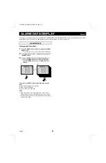
1
Press the MENU button 8 times to display the (VCR
SET) menu.
2
Press the
l
button to highlight the setting to modify,
then using the + (or –) button select the desired setting.
Following this procedure, select the settings for VCR MODE,
REC SPEED and ALARM REC SPEED.
3
☞
Press the
l
button to go to the next menu (VIDEO
LOSS SET), (RS232C SET),
☞
Press the MENU button to go to the next menu
screen, or
☞
Press the EXIT button to exit the menu display.
VCR SET menu
If the VCR is not Equipped with a SW (switching) Output
Connector
VCR MODE
TLS:
If using a timelapse VCR. (Default setting)
REAL: If using a real time VCR.
REC SPEED
The recording speed settings on this unit correspond to
recording durations on a E-180 tape.
With a timelapse VCR
Set the recording speed to match the recording speed of the
timelapse VCR.
The available speeds are: 003 (3H) (Default setting), 012
(12H), 024, 048, 072, 096, 120, 168, 240, 360, 480, 720, 960
(960H)
With a real time VCR
Set the recording speed to match the recording speed of the real
time VCR.
The available speeds are: 006 (6H) (Default setting), 018 (18H),
030, 048, 072, 096, 120, 168, 240, 360 , 480, 720, 960 (960H)
NOTE: Real time VCRs speed is based on a E-240 cassette
tape. When setting this unit to 6H, 18H or 30H, refer to
the table 1 for the speed correspondence, and select
the speed on the VCR accordingly.
Table 1
REC SPEED setting
Recording speed setting on the
real time VCR
006 (6H)
8H (8-hour mode)
018 (18H)
24H (24-hour mode)
030 (30H)
40H (40-hour mode)
ALARM REC SPEED
With a timelapse VCR
Set the recording speed to use when an alarm trigger is received to
match the alarm recording speed of the timelapse VCR.
The available speeds are:
003 (3H) (Default setting), 012 (12H), 024 (24H), NC, F3
NC:
When an alarm trigger is received, the recording speed is
not changed and stays as set under “REC SPEED”.
F3:
Use this setting when using the SW output terminal on a
timelapse VCR that does not output a switching signal in
3H mode.
With a real time VCR
Set the recording speed to use when an alarm trigger is received to
match the alarm recording speed of the real time VCR.
The available speeds are:
006 (6H) (Default setting), 018 (18H), NC, F6
NC: When an alarm trigger is received, the recording speed is
not changed and stays as set under “REC SPEED”.
F6: Use this setting when using the SW output terminal on a real
time VCR that does not output a switching signal in 6H mode.
If the VCR is Equipped with a SW (switching) Output
Connector (using the VCR switching signal)
Make the connection from this unit to the VCR SW output
connector. The video signal output by this unit will be
automatically switched to the recording speed according to the
switching signal output by the VCR (switching pulse setting on
the VCR).
The (VCR SET) menu “REC SPEED” and “ALARM REC
SPEED” items do not need to be set.
If a switching signal is not output at the switching terminal
Some VCR models may not output a switching signal in 3H or
6H mode. In such a case, make the settings as indicated in the
table below.
VCR SET menu settings
Timelapse VCR
Real time VCR
REC SPEED
003 (3H)
006 (6H)
ALARM REC SPEED
003 (F3)
006 (F6)
NOTE: When the alarm recording speed is set to F3 or F6, the
recording speed is fixed to 3H or 6H. Therefore, when
using a speed other than 3H or 6H, do not use the F3 or
F6 setting.
2
(Timelapse VCR)
(Real time VCR)
(VCR SET)
VCR MODE TLS
REC SPEED 003 H
ALARM REC SPEED 003 H
<VIDEO LOSS SET>
VIDEO LOSS ON
DATA ON
DISPLAY FREEZE
<RS232C SET>
DATA SPEED
19200
(VCR SET)
VCR MODE REAL
REC SPEED 006 H
ALARM REC SPEED 006 H
<VIDEO LOSS SET>
VIDEO LOSS ON
DATA ON
DISPLAY FREEZE
<RS232C SET>
DATA SPEED
19200
LIVE
QUAD
L8FH5/XE (MPX-CD4P, MD4P GB) 1999. 12. 2
English
31

