background image

Working principle analysis of the unit


The RF signal received by antenna will be sent to tuner TUN601, then IF signal will be obtained 

through high amplified and mixed frequency. After pre-intermediate amplified by V608, it will be sent 
to acoustic surface-wave Z605 to do IF filter and get better IF characteristics, then it will be sent to 
N602 (TDA4470) to do intermediate amplification, phase-lock loop VCO and synchronous wave 
detection to get the video signal TV-V; after pre-intermediate amplification IF will also be sent to 
acoustic surface-wave Z604 to do filter at the same time, the it will be sent to N404 to do 
intermediate amplification and output the second sound intermediate frequency signal TV-SIF.   

TV-V output from TDA4470 and TV-SIF will be sent to the main IC N304(MST9E89DL) 
Video and audio signals of AV/S, VGA, YPbPr will be sent to MST9E89DL too. 
3 groups HDMI after PS321 selecting, their video and audio signal will be sent to MST9E89DL.   
RGB of SCART1, AV, S-Y and S-C of SCART2 will also be sent to MST9E89DL, their audio 

signal and YPbPr, AV/S audio signal via audio switch HEF4052BT selection to MST9E89DL. 

The main IC N304(MST9E89DL) is a high performance and fully integrated IC, which can 

realize HDMI interface processing, video decoding, video switch selection, A/D and D/A conversion, 
interlace/de-interlace processing, modes conversion, OSD and low-voltage differential output, etc. 
And it also has functions of audio selection, processing and MCU. 

The video signal via MST9E89DL processing, output 4 pairs differential signal and 1 pair clock 

signal for LCD panel display. TV-V from TDA4470 after video double amplifying and sent to 
SCART1 as AV-OUT. AV processed by MST9E89DL after quadruple amplifying and output as 
AV-OUT and SCART2 AV-OUT. 

The audio signal via MST9E89DL processing, it will be sent to N206 (BH3547F) amplifying to 

earphone. The audio signal will also sent to sound amplifier N203 (TPA3120-D2) amplifying to 
speaker. TV-L/R processed by MST9E89DL will be sent to SCART1 for AV-OUT, at the same time, 
TV-L/R and AV-L/R will output together as the audio output of AV-OUT and SCART2 AV-OUT. 


Wor

W

king pr ncip

ple a a ysis of the unit

T e audio signa

gnaal v

l via MST

T9E89

oo

g to

ing

ify

mpl

am

F)

47F

3354

(B

06 

N2

o N

t t

en

e s

e s

b

will

g,

sing

g

Summary of Contents for LCD-42XR8KH

Page 1: ...LCD TV SERVICE MANUAL LCD 42XR8KH PRODUCT CODE No REFERENCE No SM0915048 1 682 346 30 PAL SECAM NTSC AV FILE NO PRODUCT CODE No R ...

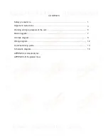
Page 2: ...ons Alignment instructions Working principle analysis of the unit Block diagram IC block diagram Wiring diagram Troubleshooting guide Schematic diagram APPENDIX A Assembly list APPENDIX B Exploded View 1 3 6 7 8 12 13 18 CONTE ...

Page 3: ...the power off immediately and do not move anything on the module lest it should cause fire or electric shock due to contact with the high voltage or short circuit 2 6 Should there be smoke abnormal smell or sound from the module please shut the power off at once Likewise if the screen is not working after the power is on or in the course of operation the power must be cut off immediately and no mo...

Page 4: ...ance of picture residue on the screen as commonly called ghost shadow The extent of the residual picture varies with the maker of LCD screen This phenomenon doesn t represent failure This ghost shadow may remain in the picture for a period of time several minutes But when operating it please avoid displaying still picture in high brightness for a long time 3 Points for attention during installatio...

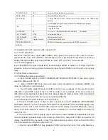
Page 5: ...VOL to adjust value items press MENU repeatedly to exit 3 1 Initialization Enter factory menu select OPTION and HOTEL OPTION sub menu adjustment of items to see table1 Table1 sub menu adjustment Items Preset Introduce HOTEL 0 1 HOTEL OPTION of factory menu is optional 0 HOTEL OPTION of factory menu is not optional LOGO 1 1 display LOGO in no signal or turn on 0 no LOGO display ADC PRESCALE 00A adj...

Page 6: ...TEMP sub menu and select color temperature of standard 9300K the value of coordinate is recommended c Fixed B GAIN adjust R GAIN G GAIN to let the color coordinate of the seventh level be 285 293 Fixed BOFF adjust R OFF G OFF to let the color coordinate of the second level be 285 293 and the brightness is about 3nit 10nit Repeat adjust R GAIN G GAIN R OFF and G OFF until the color coordinate of th...

Page 7: ...rminal Insert VGA terminal input VGA format signal of 640X480 60 Hz and check if the display is normal 5 4 HDMI terminal Insert HDMI terminal input 640X480 60Hz signal check if the display is normal Check HDCP function 5 5 check sound channel Check the speaker and earphone of each channel 5 6 RS232 terminal Insert the earphone wire to COM port check the long distance control function with special ...

Page 8: ...o signal and YPbPr AV S audio signal via audio switch HEF4052BT selection to MST9E89DL The main IC N304 MST9E89DL is a high performance and fully integrated IC which can realize HDMI interface processing video decoding video switch selection A D and D A conversion interlace de interlace processing modes conversion OSD and low voltage differential output etc And it also has functions of audio selec...

Page 9: ...O TUNER TV V TV SIF AV L R SCART1 V OUT TV L R SCART2 L R OUT AV L R OUT AV OUT CVBS SCART2 V OUT SCART1 L R OUT TV L R LCD TV CONTROLLER MST9E89DL AUDIO SW HEF4052 AUDIO AMP BH3547F PS321 EEPROM FLASH DDR PANEL EAR PHONE EDID 24C02 IF AMP TDA4470 HDCP KEY 2 AMP 4 AMP SAW SPEAKER AUDIO AMP TPA3120D2 EDID 24C02 Block di gram SC C C CA AR C ...

Page 10: ...terlacers two scaling engines the MStarACE 3 color engine an on screen display controller an 8 bit MCU and a built in output panel interface By use of external frame buffer PIP POP is provided for multimedia applications Furthermore 3 Dvideo decoding and processing are fulfilled for high quality TV applications To further reduce system costs the MST9E89DL also integrates intelligent power manageme...

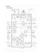
Page 11: ...9 2 TDA4470 2 2 TDA4470 ...

Page 12: ...2 can drive stereo speakers as low as 4ȍ The efficiency of the TPA3120D2 eliminates the need for an external heat sink when playing music The gain of the amplifier is controlled by two gain select pins The gain selections are 20 26 32 36 dB The outputs are fully protected against shorts from GND to ROUT or LOUT and output to output shorts with an auto recovery feature ...

Page 13: ...11 ...

Page 14: ...Wiring diagram power board power board panel IR board main board main power output key IR tuner power amplifier power audio output speaker signal signal connection board key board Wiri W ng d ag am m mai l ...

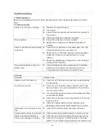
Page 15: ...n professional radio station and cellular phone 1 2 TV set Symptoms Possible cause Unable to switch the power on z Check to see if the power plug has been inserted properly into the socket No picture and sound z Check to see if the power supply of liquid crystal TV has been switched on As can be indicated by the red LED at the front of the TV set z See if it s receiving the signal that is transmit...

Page 16: ...e distance or angle from the monitor z Check if there is any obstruct between the remote control and the TV set z Check if the remote control signal receiving window is exposed to strong fluorescence No picture and sound but only hash z Check if the antenna cable is correctly connected or if it has received the video signal correctly Blur picture z Check if the antenna cable is correctly connected...

Page 17: ...the unit or remote sensor control and check the indicator Check if the PIN3 of X401 on main board is high level Check if the PIN11 of X403 in main board is high level Check power supply board Check the panel LVDS wires and back light board yes no no red blue no yes no yes Check N304 and its periphery Check N304 and its periphery 2 2 Tr 2 1 N 2 uble o ra ho te oting g gu de Ch heck N3 vel lev igh s...

Page 18: ...Adjust main board again Which channel is no signal Check N304 and its peripery Check if TUNER601 pin11 IF output is normal Check N601 and its periphery no yes yes HDMI VGA YPRPB TV yes no yes Does display OSD menu in screen when press menu button yes no yes no Check if there is 1VPP signal or noisy of X405 TP601 on main board no Check TUNER601 and its periphery no 2 2 H 2 ave aster but no o pi tur...

Page 19: ...rd Check the wave of pin 5 6 of N203 Check the wave of N602 pin 24 Check the wave of TUNER601 pin 11 Check N203 and its periphery Check N304 and its periphery Check N602 and its periphery Check TUNER601 and its periphery yes no yes yes yes no no no 2 3 N 2 o so nd pher erip ph ...

Page 20: ...MIAN BOARD ...

Page 21: ...MIAN BOARD ...

Page 22: ...MIAN BOARD ...

Page 23: ...MIAN BOARD ...

Page 24: ...MIAN BOARD ...

Page 25: ...MIAN BOARD ...

Page 26: ...INTERFACE CONNECTION ...

Page 27: ...KEY ...

Page 28: ...IR ...

Page 29: ...POWER ...

Page 30: ...273120001 SCART connection board XI6FY0064610 Key board XI6HE0130510 IR board XI6HU0230910 Power board XI6HU0422010 Remote control XI6010Y06006 Panel XI5203428305 RC Y60 0F T420HW04 V2 APPENDIX A Main assembly LCD 42XR8KH MAIN COMPONENT AND IT S NO APP A NDIX A Main n ass sembly LCD 42XR8K NO IT PON COM ...

Page 31: ...APPENDIX B Exploded view LCD 42XR8KH APPENDIX B Exploded v view LCD 42 ...

Page 32: ...VIEW NO DESCRIPTION 1 Front cabinet 2 Speaker 3 Panel 4 Power board 5 SCART connection board 6 Back cabinet 7 Stand 8 IR board 9 Key board 10 Main board 11 User manual 12 Remote Control PAR NO P LIS O EXP RIP LO IO DED VIEW ...

Page 33: ...22010 Power board 1 5 XI6FY0064610 SCART connection board 1 6 XI5H240WH02B Back cabinet 1 7 XI6151130010 Stand 1 8 XI6HU0230910 IR board 1 9 XI6HE0130510 Key board 1 10 XI6HK02001A0 Main board 1 11 XI5944034270 User manual 1 12 XI6010Y06006 Remote control 1 Only the parts in above list are used for repairing Other parts except the above parts can t be supplied PAR D P LIS ...

Page 34: ... your TV flat screen down on a table or bench Make sure that you put down a soft cushion or cloth so that your TV is not scratched 3 Using the supplied five M5 screws to tighten the stand securely Accessories 1 Stand 1 unit 2 M5 Screw 5 units Tighten with five M5 screws 2 Align the fixating holes of the stand with the protruding holes on the TV bottom stand column fully attach the stand to the sta...

Page 35: ...all mounting connectors into the four calabash shaped holes on the wall mounting holder Fig 5 Take out these parts from the box Wall Mounting Holder Expansion Bolt Wood Screw Combination Screw Wall Mounting Connector Fig 3a Fig 4 Fig 6 Fig 7 3a Screw 4pcs expansion bolts to fix the wall mounting holder on the wall 6 Let the display unit slowly slide down to the end of the calabash shaped hole Fig ...

Page 36: ...June 2009 ...

Reviews: