3
Alignment instructions
1. Test equipment
PM5518 (video signal generator)
VG-848 (VGA and HDMI signal generator)
CA210 (color analyzer)
2 Alignment flow-chart
The alignment flow-chart is shown as fig-1
Fig-1 adjustment flow-chart
3 Unit adjustments
Connect all the boards according to wiring diagram, connect with power and observe the display.
Method for entering factory menu:
press “INPUT”, “2”, “5”, ”8” and “0” in turn to enter factory
menu; press “CH+” and “CH-” to select adjustment items and press “VOL+” and “VOL-” to adjust
value items, press “MENU” repeatedly to exit.
3.1 Initialization
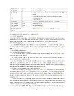
Enter factory menu, select “OPTION” and “HOTEL OPTION” sub-menu, adjustment of items to see
table1.
Table1 sub-menu adjustment
Items Preset
Introduce
HOTEL
0
1: HOTEL OPTION of factory menu is optional
0: HOTEL OPTION of factory menu is not optional
LOGO
1
1: display LOGO in no signal or turn on
0: no LOGO display
ADC PRESCALE
00A
adjust according the power consumption
Check
DDC, HDCP KEY, FLASH
Factory initialization setup
IF channel AFT voltage of TV and AGC voltage adjustment
White balance adjustment
Performance check
Preset ex-factory
Combined test for general assembly
A
cco ing the pow
Alig
A
nment nstructi n
ch
Summary of Contents for LCD-42XR8KH
Page 11: ...9 2 TDA4470 2 2 TDA4470 ...
Page 13: ...11 ...
Page 20: ...MIAN BOARD ...
Page 21: ...MIAN BOARD ...
Page 22: ...MIAN BOARD ...
Page 23: ...MIAN BOARD ...
Page 24: ...MIAN BOARD ...
Page 25: ...MIAN BOARD ...
Page 26: ...INTERFACE CONNECTION ...
Page 27: ...KEY ...
Page 28: ...IR ...
Page 29: ...POWER ...
Page 31: ...APPENDIX B Exploded view LCD 42XR8KH APPENDIX B Exploded v view LCD 42 ...
Page 36: ...June 2009 ...


