GB–23
ELECTRICAL CONNECTIONS
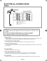
WIRING
(White)
(White/Black)
(Gray)
(Gray/Black)
(Green)
(Green/Black)
(Violet)
(Violet/Black)
Left
Speaker
Right
Speaker
Do Not
Connect
Front Left
Speaker
Front Right
Speaker
Rear Left
Speaker
Rear Right
Speaker
(White)
(White/Black)
(Gray)
(Gray/Black)
(Green)
(Green/Black)
(Violet
(Violet/Black)
Do Not
Connect
2-speaker System
4-speaker System
+12V Constant Power Supply (Yellow)
+12V Accessory/Switched (Red)
Ground Wire (Black)
Power Antenna/Amplifier Turn On (Blue)
ANTENNA PLUG
ANTENNA SOCKET
In the case of a 2-speaker system,
tape the ends of unconnected
terminals to prevent short circuit
Tel mute (Brown)
CAUTION
• DO NOT connect any speaker wires to the metal body or chassis of the
vehicle.
• DO NOT connect the speaker common (–) wires to each other.
• Connect each speaker wire directly to each speaker terminal.
• All speaker common (–) wires must remain floating.
1
Antenna socket
• Insert the plug from the antenna installed in your vehicle into this socket. (If your vehicle has a dual
antenna system, a dual antenna to single antenna cable adaptor may be required.)
2
+ 12V Constant Power Supply (Yellow)
• Connect this wire to the +12V power terminal which receives power continuously.
3
+12V Accessory/Switched (Red)
• Connect this wire to the terminal which receives power while the ignition switch is ON or in the ACCES-
SORY position.
4
Ground wire (Black)
• Connect this wire to the vehicle chassis.
5
Power Antenna/Amplifier Turn On (Blue)
• Connect this wire to the control terminal of a Power Antenna or an external amplifier.
• When not using a Power Antenna or an external amplifier, this wire is not connected.
6
Tel mute (Brown)
• Connect to the terminal that is grounded when either the telephone rings or during conversation.
780RDS/CDC_body
8/20/02, 5:58 PM
23

