


-9-
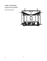
C5KEV
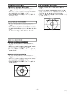
HORIZONTAL CENTRING ADJUSTMENT
1. Receive circular pattern and set screen mode to
“FULL”.
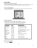
2. Enter to the service mode and select mode “IMAGE”,
and select item no. 2 “IMAGE 2.P H-P”.
3. Press the LEVEL+ or LEVEL - button to adjust the
horizontal centre.
1. Receive circular pattern and set screen mode to
“FULL”.
2. Set controls for brightness and contrast to maximum.
3. Connect high-voltage meter to the anode of CRT and
GND.
4. Confirm that voltage is 27.0±1.0kV for 21” model
VERTICAL CENTRING ADJUSTMENT
1. Receive circular pattern and set screen mode to
“FULL”.
2. Enter to the service mode and select mode “IMAGE”,
and select item no. 15 “IMAGE1.P VPH”.
.3 Press the LEVEL+ or LEVEL - button to adjust the
vertical centre.
VERTICAL HEIGHT ADJUSTMENT
1. Receive circular pattern and set screen mode to
“FULL”.
2. Enter to the service mode and select mode “IMAGE”,
and select item no. 5 “IMAGE 5.P V-A.
3. Press the LEVEL+ or LEVEL - button to adjust the
vertical height.
1. Receive circular pattern and set screen mode to
“FULL”.
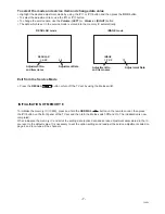
2. Enter to the service mode and select mode “REGU-
LAR”, and select item no. 8 “REGULAR 8 OSD”. The
OSD test bar will appear on the top of screen.
3. Press the LEVEL+ or LEVEL - button to adjust prop-
er OSD positioning.
❚❚❚❚❚❚❚❚❚❚❚❚❚❚❚❚❚❚❚❚
OSD POSITIONING ADJUSTMENT
VERTICAL ADJUSTMENT
HIGH-VOLTAGE CONFIRMATION
HORIZONTAL ADJUSTMENT
Summary of Contents for CE21CM1F-C
Page 26: ... 26 C5KEV ...
Page 27: ... 27 C5KEV ...