−
16
−
3.
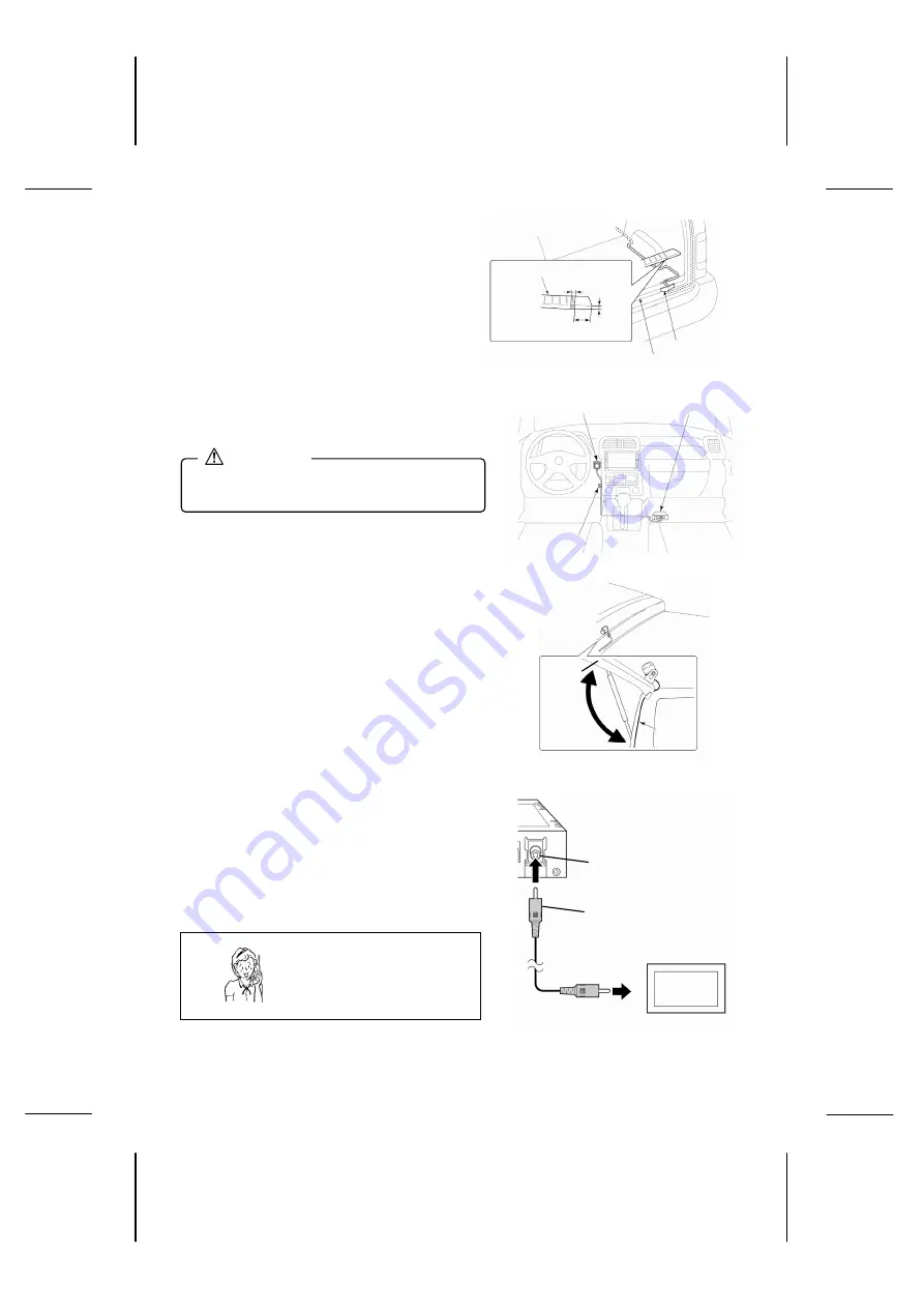
Route the camera cable to the ECU box positioned
inside the vehicle and clamp it using the cable
clamps.
Insert the cable into the slit provided in the
waterproof pad and attach the waterproof pad to
the weather strip on the vehicle at the point where
the cable enters the vehicle.
4.
Route the control switch cable to the ECU box and
secure it with cable clamps.
•
Confirmation of camera installation and
cable routing
Make sure the camera and cable do not interfere
when operating the liftgate, and that the cable does
not contact the edge of the liftgate.
• Connecting Video Cable
Connect the video output cable to the camera input
terminal or video input terminal on the navigation
system or external monitor. (Read the separate
instruction manuals for these devices to connect them
correctly.)
Luggage finish plate
Weather strip
Position with no ribs on the rear side
Waterproof pad
0.1 in
0.1 in
•
Route the cable so that it does not obstruct
vehicle operation.
CAUTION
ECU box
Control switch
Cable clamp
Liftgate
Cable
Camera
ECU box
Navigation system
or external monitor
Video output
cable (Yellow)
Video output connection
terminal (Yellow)
(Yellow)
To Video input terminal
Connect to camera input terminal or
video input terminal on navigation
system or external monitor
Need help? Call
1-800-421-5013
Summary of Contents for CCA-BC200
Page 2: ... 1 ...


