background image

Connecting other Equipment

15

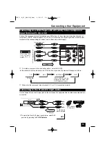
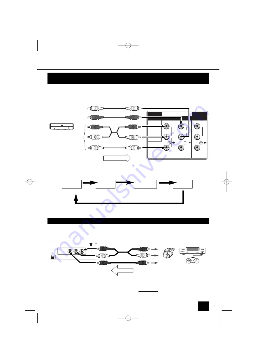
Connect the component output terminal on your DVD player to the component video input terminal of
this product. (NOTE: When a signal of Y,C

b

,C

r

/Y,P

b

,P

r

is received, the output signal from monitor output

terminal will be corresponding but without colour (black and white image).)

Connecting to a DVD Player with AV1(DVD) Video Component
Input Terminal (Y, Cb or Cr)

TV mode

AV1

AV1(DVD)

28

AV2

In this connection status, whenever the TV/AV button is pressed, the mode will change as follows:

Make sure the component video terminal (Y, C

b

or C

r

) is connected correctly. 

To watch a program in this connection status,  select AV1(DVD).

(This AV1(DVD) will be
displayed for model with
DVD Component input.)

Connecting to the Front AV2 Input Jacks 

It is convenient to use the AV input jack on the front panel for equipment that is often connected and dis-
connected.

AV2

To watch the Front AV2 video input picture, select AV2 

position by pressing the 

TV/AV Selector

.

Y

MONITOR OUT

AV1/DVD

C

R

C

B

R

L

(MONO)

VIDEO

R

L

INPUT

V

D

E

O

I

PLAY

To

 V

ideo Component Output

To Audio Output (Left)

To Audio Output (Right)

DVD Player with
Video Component
(Y, CB, CR) or (Y,
PB, PR)

VIDEO

AV2 IN

TV

L-AUDIO-R

Video Camera,

TV Game etc.

To video and
audio outputs

PLAYBACK

(Stereo)

INST. M_29_BA6V-A(Aus)  4/10/07  11:14 AM  Page 15

Summary of Contents for CA29FS1

Page 1: ...1 CA29FS1 CP29YS2 CA29YS2 INSTRUCTION MANUAL Colour Television Flat Screen Multi System CATV Hyper Band 256 Programmes with Automatic Tuning AV Stereo Sound System INST M_29_BA6V A Aus 4 10 07 11 14 AM Page 1 ...

Page 2: ... other source of the heat Do not stand the television receiver directly on other products which give off heat E g video cas sette players audio amplifiers Do not block the ventilation holes in the back cover Adequate ventilation is essential to prevent failure of electrical components Do not squash power supply cord under the tele vision receiver Warning High voltages are used in the operation of ...

Page 3: ...This TV set provides a self automatic tuning and sorting system function called Plug Play It automatically begins searching and storing of all available channels when switching on the TV set for the first time 2 Press any of the control buttons to make the ending message disappear Or will automatically return to normal TV display after 10 seconds After completing this procedure the programme posit...

Page 4: ...ector Programme UP DOWN VOLUME MENU TV AV Selector Audio Input Jack Right AV2 Audio Input Jack Left AV2 Video Input Jack AV2 Headphone Jack Mini Stereo Jack Model CP29YS2 CA29YS2 VIDEO AV2 IN TV AV MENU CH L AUDIO R Mains ON OFF button Remote Control Detector Stand by and Power Indicator Programme UP DOWN VOLUME MENU TV AV Selector Audio Input Jack Right AV2 Audio Input Jack Left AV2 Video Input J...

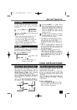
Page 5: ...NO button Programme DOWN button BASS EXPANDER button SOUND MODE button This button is not used SOUND SYSTEM button DIGIT button Battery Installation of the Remote Control Transmitter General Operation Important Be sure to set the Mains ON OFF switch to the off position if the power failure occurs while viewing To switch on or off the TV Press the Mains ON OFF button The power of the TV is turned o...

Page 6: ...ERNATE button and the pro gramme position will alternately select the previous position and the present position To display the on screen indications press the RECALL COLOUR SYSTEM button Screen display disappears after about 5 seconds 29 AUTO OFF 0 30 ON 3 30 6 Off Timer On Timer Programme Position BG Sound System Colour System RECALL Sound Mute P P ALTERNATE Press the PICTURE MODE button to sele...

Page 7: ...d on by ON TIMER 2 Press the VOLUME or button The set time will be increased or decreased by 10 minutes each time the button is pressed the maximum time which can be set is 24 hours When the ON TIMER has been set the colour of Standby and Power Indicator changes to yellow OFF TIMER ON TIMER 3 Use Direct programme Selection to insert pro grammme position for when TV is switched on by ON TIMER see p...

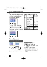
Page 8: ...WN button in the Semi auto or Manual Tuning mode Then press the VOLUME or button to select a optimum sound system Picture Adjustment BRIGHT TINT CONTRAST SHARPNESS SELECT ADJUST BACK P P M EXIT COLOUR Picture Adjustment Item COLOUR Adjusts colour intensity BRIGHT Adjusts picture brightness CONTRAST Adjusts picture contrast TINT Adjust colour tints Displayed only on NTSC or NTSC4 43 system signal r...

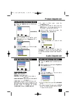
Page 9: ...0 seconds BRIGHT SHARPNESS CONTRAST WHITE TONE FINE TUNING COLOUR Audio Adjustment 1 Press the MENU button for MAIN menu dis play BASS EXPANDER OFF BALANCE SURROUND OFF SELECT ADJUST BACK P P M EXIT BASS TREBLE Audio Adjustment Item BASS Bass Adjustment TREBLE Treble Adjustment BALANCE Left right speaker volume balance adjustment BASS EXPANDER Operates BASS EXPANDER on and off SURROUND Operates SU...

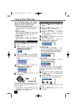
Page 10: ...UME button to start channel tuning SEARCH SYSTEM POSITION START 1 AUTO SIF BG MODE AUTO 1 Press the MENU button for MAIN menu display 2 Select PRESET by pressing the Programme UP or DOWN button 3 Press the VOLUME or button for PRESET menu display On entering PRESET display Automatic Tuning will be selected initially 4 Select SEMI or MANUAL by pressing the VOLUME or button Semi AutoTuningandManualT...

Page 11: ... channel between pro gramme position 6 and programme position 12 6 12 SWAP 6 AND 3 Press the DIGIT button 1 button and then 2 button on the remote control to enter programme number 12 For example to enter programme number 3 press 3 button only SWAP 6 AND 12 6 12 4 Press the SWAP button 12 SWAPPING 1 Enter to SEMI AUTO or MANUAL tuning mode Refer to page 10 2 Select POSITION with the Progamme UP or...

Page 12: ...ure will disappear and 15 will be dis play on the screen The private position setting is now completed 3 Press the MENU button Private position is used to restrict of pro gramme positions that you do not want others to watch Any position can be set as the Private position BG How to set the Private Position 12 15 AUTO B G 15 15 1Select private position In this case position 15 2 Press and hold the ...

Page 13: ... and left channels to the respec tive right and left AUDIO IN terminals Then select STEREO channel of the audio channel in the TV set with the remote control button A B STEREO MONO Each time the button is pressed the AV Stereo mode is changed as follow A B When the stereo signal is inputted from the right and left audio input terminals each time the SURROUND button is pressed or selection of On sc...

Page 14: ...e selected Note Pressing either of the PROGRAMME UP or DOWN buttons of the remote control or the TV will return the TV to the TV mode AV1 AUTO AV1 PAL AV1 NTSC4 43 AV1 NTSC Selecting the Colour System in AV Mode S VHS VCR DVD Player Connection For Model CP29FS1 CA29FS1 To display high grade picture S VHS video connect to S VIDEO terminal Using the S VIDEO terminal to connect to a DVD player instea...

Page 15: ...l Y Cb or Cr is connected correctly To watch a program in this connection status select AV1 DVD This AV1 DVD will be displayed for model with DVD Component input Connecting to the Front AV2 Input Jacks It is convenient to use the AV input jack on the front panel for equipment that is often connected and dis connected AV2 To watch the Front AV2 video input picture select AV2 position by pressing th...

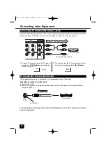
Page 16: ...oadcasts and for video dubbing from AV1 or AV2 input terminals Connecting to the Monitor Output Jacks TV mode Aerial Socket The AV apparatus can also be connected to the aerial socket of your TV receiver Presetting to watch the video input 1 Playback the VCR 2 Tune a VCR playback in programme position that you want See Semi Auto Tuning and Manual Tuning on pages 10 VCR for playback PLAYBACK AV Con...

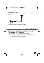
Page 17: ...Clean the cabinet with a soft cloth dampened with a mild household detergent and warm water Dry thoroughly Note NEVER spray liquids on the screen because they can run down and drip onto the chassis This may cause component failure not covered under Warranty Connect the cable with a plug from a UHF or VHF aerial to the aerial socket on the cabinet back Connecting Outdoor Aerial Aerial Cable Aerial ...

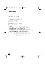
Page 18: ... Separate DIN Jack Input Model CA29FS1 CP29FS1 only Video Inputs Phone Jack x 2 1 0Vp p impedance 75 Ω Audio inputs Phone Jack L R x 2 436mVrms impedance more than 40KΩ Video monitor outputs Phone Jack x 1 1 0Vp p impedance 75 Ω Audio monitor outputs Phone Jack L R x 1 436mVrms impedance less than 600Ω Headphone Jack Mini Stereo Jack x 1 Model CA29FS1 CP29FS1 only Dimension Model CP29FS1 CA29FS1 8...

Page 19: ... on the remote control Adjust Volume May be station trouble Try a different channel Select other sound system See Setting of the Sound System on page 8 9 Remote Control will not work Check batteries Replace batteries Check if TV set is plugged in Aim remote control towards front of TV Cannot select or scan some channels Channel may be removed from memory Add channel to memory manually See Skip Cha...

Page 20: ...SANYO ELECTRIC Co Ltd Part No 1AA6P1P5399 A BA6V A FC6 B INST M_29_BA6V A Aus 4 10 07 11 14 AM Page 20 ...

Reviews: