


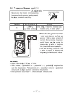
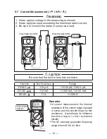
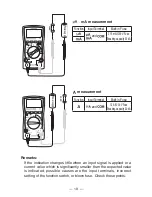

— 10 —
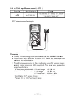
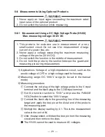
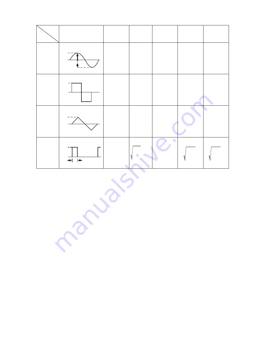
Input Waveform
0 to PEAK
Vrms
Average
Value
Crest
Factor
Form
Factor
Root Mean
Square Value
Vavg
Vp/Vrms Vrms/Vavg
Sinusoidal
wave
Square
wave
Chopping
wave
Pulse
=1.414 =1.111
Vp
Vp
Vp
1
0
0
p p
Vp
Vp
0
Vp
−
Vp
2
√
=0.707 Vp
−
2
Vp
π
=0.637 Vp
2
√
Vp
−
2
√
2
π
2π
π
π
Vp
Vp
1
π
2π
2π
−
Vp
3
√
=0.577 Vp
−
Vp
2
=0.5 Vp
−
2
3
√
=1.155
3
√
=1.732
2π
τ
0
Vp
−
τ
2π
・
Vp
−
τ
2π
・
Vp
−
2π
τ
−
2π
τ
Vp
Voltages of Various Waveforms
s
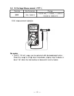
This meter employs AC coupling for AC measurement.
The DC components in input signals are cut.
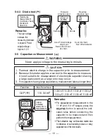
4-11 Connection with PC
The multimeter is capable of DMM data communication using the
USB interface.
When the multimeter on which the optional USB optical
communication unit (KB-USB773) is mounted is connected to a PC,
the multimeter will output data to the PC. It is required to purchase
the optional PC link software (PC Link7) for this operation.
For details, refer to the Help for the optional PC link software (PC
Link7).
<Connection of cable and multimeter>
①
Remove the light-shield rubber cap from the rear case of the
multimeter.
②
Connect the USB optical communication unit to the multimeter.
Summary of Contents for PC773
Page 1: ...PC773 DIGITAL MULTIMETER 取扱説明書 INSTRUCTION MANUAL ...
Page 2: ......
Page 35: ...PC773 DIGITAL MULTIMETER INSTRUCTION MANUAL ...
Page 70: ...MEMO ...
Page 71: ......