


DRAWING No.EM7000 09-1306 2040 2040
— 56 —
Specifications and external appearance of the product described
above may be revised for modification without prior notice.
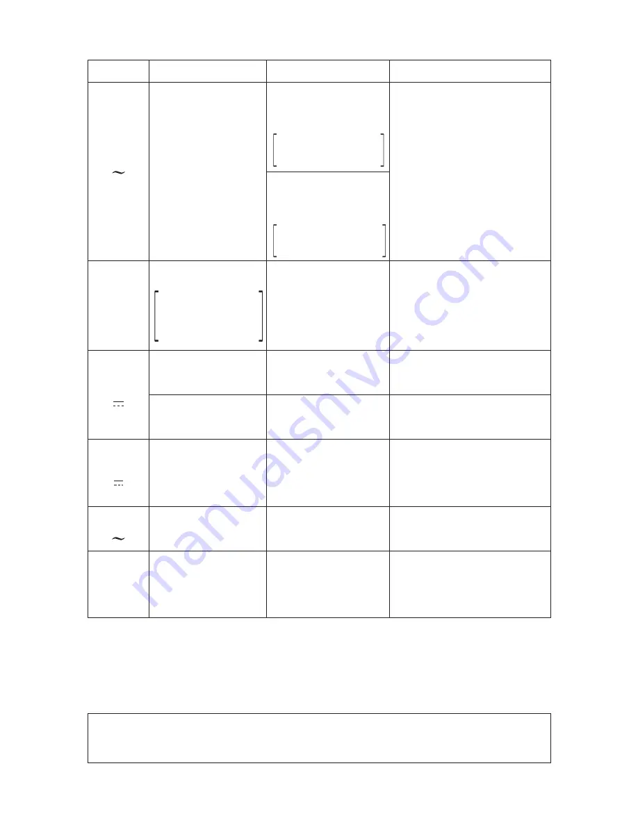
DCA
( )
±
DCA
( )
0.12 µA
0.3 m/3 m/30 m/300 mA
8.4 Vp-p
±
3 % of arc
Internal impedance
Approx. 2.5 M
Ω
(50/60 Hz)
AF output
(dB)
-
10~51 dB
0 dB=0.775 V(1 mW)
in 600
Ω
inpedance
circuit
6 A
±
3 % Against full scale
±
4 % Against full scale
A voltage drop by fuses
is excluded : 300 mV
Continuous measurable
time max. 30 s
±
0.06 µA
±
0.15 m/1.5 m
/15 m/150 mA
±
7 % Against full scale A voltage drop by fuses
is excluded : 150 mV
ACA
( )
6 A
±
5 % Against full scale
(sine wave 50~60 Hz)
Continuous measurable
time max. 30 s
Resistance
(
Ω
)
2 k(X1)/20 k(X10)/
200 k(X100)/2 M(X1 k)/
20 M(X10 k)/
200 M(X100 k)
±
3 % of arc
Center value 20
Ω
(X1 range)
Max. value 2 k
Ω
(X1 range)
Release voltage : Approx. 3 V
Function Full scale value
Accuracy
Remarks
Square symmetric wave
(50 Hz Duty 50 %)
±
6 % Against full scale
50 Hz basis
40 Hz~100 kHz : within
±
3 %
ACV
( )
p-p
*
*
Above is only for measuring distorted wave voltage of 8.4 Vp-p range.
The reading is approximate value when measuring non-sine wave AC at
range of 33 Vp-p or higher.
Triangular symmetric wave
(50 Hz)
±
6 % Against full scale
50 Hz basis
40 Hz~100 kHz : within
±
3 %
Summary of Contents for EM7000
Page 1: ...EM7000 FET電子テスタ FET MULTITESTER 取扱説明書 INSTRUCTION MANUAL ...
Page 2: ......
Page 63: ...MEMO ...
Page 64: ...MEMO ...
Page 66: ......
Page 67: ......