background image

Machine Number

Code

MFG No.

INSTRUCTION MANUAL

Manual No.MEK01C(E)/1612ATEX

Original Instruction

Europe Edition

SANWA HYDROTECH CORPORATION

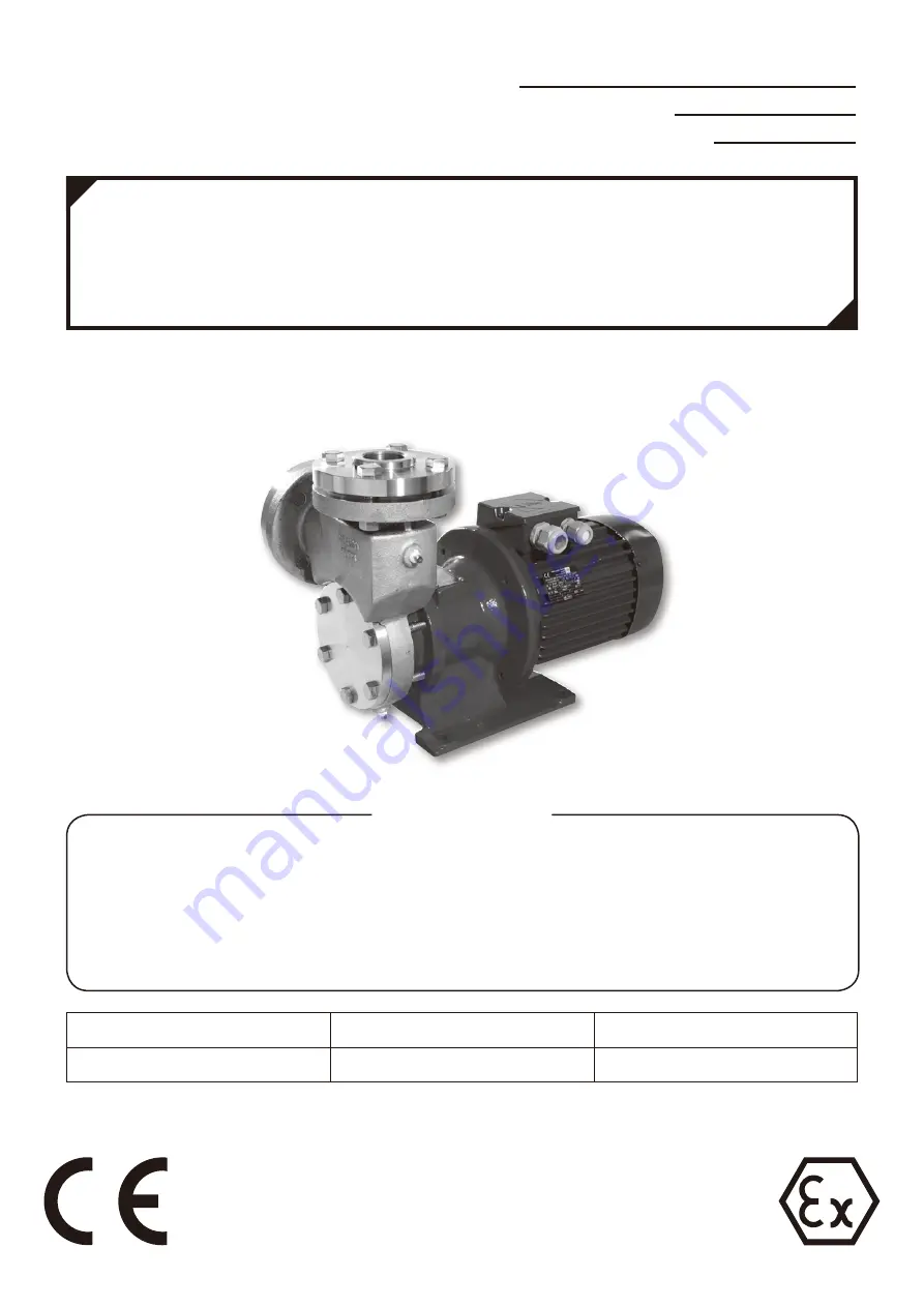
STAINLESS STEEL MAGNET DRIVE PUMP

SELF-PRIMING TURBINE PUMP


MEK

This instruction manual is for the person who actually operates the pump. 
Please be sure this manual is provided to and understood by the operator on 
the scene. If the instruction manual is also needed by personnel who install 
the pump or by a staff of a plant constructor, please let us know. We will 
supply another copy.

To the on-site operator: please enter the pump’s code and lot number above and for future 
parts order and inquiry.

Requirements

Summary of Contents for MEK Series

Page 1: ...ual is for the person who actually operates the pump Please be sure this manual is provided to and understood by the operator on the scene If the instruction manual is also needed by personnel who install the pump or by a staff of a plant constructor please let us know We will supply another copy To the on site operator please enter the pump s code and lot number above and for future parts order a...

Page 2: ...nwa Hydrotech does not assume responsibility for damage or injury re sulting from failure to follow the safety instructions contained herein Be sure therefore to follow the instructions for safe and correct usage when op erating performing maintenance or inspecting the pump The degree of potential danger as a result of improper handling or operation is indicated by the following three classificati...

Page 3: ...ure to do so could result in electrical shock Use the material which is suitable to specification of liquid Otherwise leakage occurs Operation Absolutely do not touch or come close to turning parts Doing so could result in injury caused by entanglement in the rotating parts In case of power failure be sure to turn the power off to prevent the pump from starting unexpectedly when the power is resto...

Page 4: ...lt in injury Disassembly and Assembly Be careful with hazardous liquids If pumping dangerous chemicals be sure to drain and wash well before disassembling A small amount of fluid may however remain in the screw faucet joint and engaged parts inside the pump If handling hazardous chemicals be sure to wear protective equipment such as safety glasses and rubber gloves and proceed with caution while d...

Page 5: ...not remove the name plate or warning labels Transport Beware of equipment falling or turning over during transport Be sure to use hanger bolt if the pump is equipped with one After installation however you should avoid hoisting the entire machine by the hanger bolt Before lifting check the weight of the pump by referring to the catalog etc Do not lift the pump which exceeds the rated weight of the...

Page 6: ... high temperatures If handling high temperature fluids do not place your hands etc near the casing or frame adapter Doing so could result in skin burning Do not operate the pump for pumping gases This pump is designed for pumping liquids Otherwise the pump may have a high temperature or SiC bearings and the rear casing shell may be broken No Load Operation Absolutely do not operate the pump withou...

Page 7: ...ode of operation Driving motor must have approval for the use in areas subject to explosion hazards Temperature limits When being operated to its designated use the pump s maximum surface temperature must not exceed the temperature category of the explosion protection zone Speed limits The maximum allowable speed is 1800rpm MEK201 251 or 3600rpm MEK322 402 If the pump is operated with a speed exce...

Page 8: ...e of the pump surface Do not operate the pump under these situations Shut off operation Low flow operation Dry run Operating with decoupling Maintenance If the clearance between rotating and stationary components is out of limitation it may happen that these component contact and resulting frictional heat entail excessive temperatures Ensure that bypass hole of casing and shaft is not interrupted ...

Page 9: ...er µm Micrometer mm Millimeter Flow m3 hr Cubic meter per hour L min Liter per a minute Pressure MPaG Megapascal gauge Temperature C Celsius F Fahrenheit Speed rpm Rotation per minute A weighted sound pressure level dB A Decibel Power kW Kilowatt Torque N m Newton meter kgf m Kilogram force meter Frequency Hz Hertz Viscosity mPa s Millipascal second ...

Page 10: ...f The Machinery 12 Transport and Unpacking 13 1 Transport 13 2 Unpacking 13 Preliminary Check 14 Pump Model Identification 15 1 Pump Size 15 Type Pump Code 15 Pump Specification 16 1 Design Pressure 16 2 Casing Piping Connection 16 3 Viscosity 16 4 Magnet Coupling 16 5 Motor 16 6 Parts Specifications of Liquid Temperature Range 17 7 Ambient Temperature 17 8 Speed Limit 17 9 Maximum and Minimum Flo...

Page 11: ...off before performing inspections 26 2 Operation 26 Operation and handling 26 3 Shutting Down 27 Maintenance and Inspection 30 1 Routine Inspection 30 2 Configuration and Location of Part 31 Parts 31 Configuration 32 3 Order of Disassembly and Assembly 33 4 Checking parts dimension 36 5 Optimal Tightening Torque for Bolts and Nuts 37 Troubleshooting 38 Repairs and Warranty 40 ...

Page 12: ... before attempting to use the pump Equipment Failure Accident Prevention and Safe Operation Checks Pre Operation Checks The power source wiring and connection piping priming air purging and rotation direction should be checked before starting operation Checks for Test Operation and Actual Operation Current voltage suction pressure discharge pressure and discharge flow rate should be checked when s...

Page 13: ...ion Liquids which could produce germs liquids which are of a dangerous nature Liquids which could directly harm the human body Preventative measures should be taken to protect special pumps and pumps used in the main production line from natural disasters unexpected accidents or equipment failure the event of which could have a disastrous effect on your production If these are impossible you shoul...

Page 14: ...r drawings to check the weight of the pump and the motor Never lift a pump that exceeds the rated load of your suspension device If you fail to heed this advice the eyebolts may be distorted and the pump may drop or fall and this may cause an injury or damage the pump The pump bearing is made of extremely rigid material and cannot endure rigorous vibration The pump should be handled with care duri...

Page 15: ...mp has not been damaged or the bolts and nuts not loosened during transport If you discover any accessories to be missing or you find something wrong with the merchandise please contact your dealer or you may contact us directly Nameplate of pump ATEX marking See Page 17 TYPE Pump Model and Pump Code See next page DATE Manufactured year and month IMP DIA Diameter of impeller inside the pump PUMP M...

Page 16: ... KD 025 1 2 3 4 5 1 Pump Model See Page 14 2 Wet end main Material 6 316SS 3 Material of Check valve TS PTFE 316SS 4 Material of Bearing Bushing Sleeve KD SiC SiC D 5 Motor Output 025 0 25kW 03 0 37kW 15 1 5 kW 22 2 2 kW 30 3 0 kW 40 4 0 kW MODEL SUCTION mm DISCHARGE mm MOTOR FRAME 201 20 20 4Pole 0 25 kW 71 251 25 25 4Pole 0 37 kW 71 322 32 32 2Pole 1 5 kW 90 2Pole 2 2 kW 90 402 40 40 2Pole 3 0 k...

Page 17: ... Note When viscosity is over 30mPa s please consult your distributer 4 Magnet coupling 5 Motor Motor 4Pole 0 55kW 80 for MEK251 is available as an option In this case the exclusive parts frame adapter and magnet coupling M are necessary PUMP SIZE DESIGN PRESSURE MPaG MEK 201 1 0 251 322 402 PUMP SIZE MAGNET COUPLING MEK 201 T 06 26 251 T 12 26 322 T 12 26 402 T 12 38 PUMP SIZE MOTOR PUTPUT kW FRAM...

Page 18: ...ing table for maximum allowable temperature of the pumped liquid in accordance with the applicable temperature category The maximum surface temperature of the pump is the highest temperature ascertained from any one of the following conditions 1 the temperature of the liquid plus 20 68 F 2 the temperature of the ambient temperature plus 20 68 F Thus the maximum liquid temperature for each temperat...

Page 19: ... Gas G 4 Protection measure c construction safety 5 Gas Group IIC 6 Temperature Class see above chapter 10 It depends on the temperature of pump liquid and ambient temperature For Dust atmosphere II 2 D c T C 1 2 3 4 5 1 Equipment Group II non mining 2 Category 2 3 Dust D 4 Protection measure c construction safety 5 Maximum surface Temperature see above chapter 10 It depends on the temperature of ...

Page 20: ...19 Declaration of Conformity ...

Page 21: ...20 ...

Page 22: ...21 ...

Page 23: ...ds on liquid temperature Refer to following table Liquid temperature C F 0 32 20 68 40 104 60 140 70 158 80 176 Suction lift height m 7 6 7 2 5 4 3 2 1 7 0 3 In the case of a liquid except the water suction height changes by saturated steam pressure and viscosity specific gravity density of liquid When liquid temperature is more than 80 C it is necessary to apply pressure in suction side of the pu...

Page 24: ...zontally or downward vertically Because the spindle part may become air pocket If it is possible the liquid in the discharge piping is frozen install a drain to remove the liquid in the discharge piping NOTE Weight of the suction and discharge piping can cause misalignment or equipment failure Be sure to provide sufficient support for the piping The piping should be as short as possible with a min...

Page 25: ...minal connecting to be performed by unqualified persons You are also obligated by law to provide an earth leakage breaker and overload protection equipment to prevent electrical shock or fire 3 Wiring Suction for Positive Pressure Suction for Negative Pressure piping diameter x 2 required for lengthly piping Suction Piping Fastener Foot Valve Screen Gate Valve Piping Support Compound Gauge D Min 5...

Page 26: ...ified by a label with the following symbol on it Once pump has been installed the earth of motor terminal box should be wired to the earth with a suitable earthing cable In addition please carry out the bonding of the plumbing if necessary Note Please ground wiring according to instruction manual of motor ...

Page 27: ...ir by opening the air purge cock while being careful not to allow high pressure to the suction piping or foot valve 2 Operation 1 After priming turn the switch on and off one or two times and make sure the rotation direction clock wise direction when viewed from the motor side is correct and that the pump operates normally When check the direction of rotation the pump must be fully filled Otherwis...

Page 28: ...n and handling Never perform cavitation or no load operation Doing so could damage the bushings Shut the pump off immediately if you discover the pump to be operating in such conditions When perform no load operation the temperature of the surface of rear casing and the journal bearing will rise If the magnet coupling slips stop the pump immediately within one minute Continuing to operate with the...

Page 29: ...erature the specific gravity viscosity vapor pressure and corrosiveness of the liquid are affected You must therefore be aware of changes in the properties of the liquids handled Variation of Performance by Specific Gravity Pump performance is affected by specific gravity of the liquids then a suitable power unit motor inner magnet coupling and outer magnet coupling must be applied by considering ...

Page 30: ...uilding If the motor is driven by inverter noise level will be increased 60Hz dB A 50Hz dB A MEK 201 70 70 251 70 70 322 72 71 402 73 72 3 Shutting Down 1 Shut the discharge valve gradually 2 Stop the motor When turned off the motor should gradually slow down to a smooth s top If it does not stop smoothly check the inside of the pump to see if everything is as it should be 3 In case of power failu...

Page 31: ...uum gauges is to be opened for measurement only Shut the gauge cock after measuring Pump operating load Discharge pressure under operation must be checked according to the figure showed on the specification plate of the pump Electric current must be lower than figure showed on the specification plate of the motor A periodic inspection should be performed at least once a year A record of periodic i...

Page 32: ... 57 Flange discharge 316SS 1 56 Check valve 316SS 1 This part cannot be separated with gasket No 54 55 Flange suction 316SS 1 54 Gasket PTFF 1 This part cannot be separated with check valve No 56 53 Plug priming port 316SS 1 R3 8 52 Plug air vent port 316SS 1 R1 8 51 Plug casing drain port 316SS 1 R1 8 45 Bushing SiC 2 This part can be replaced by manufacturer 40 Tolerance Ring 316SS 2 This part c...

Page 33: ...Impeller key 316SS 1 8 Shaft 316SS 1 4 Rear casing 316SS 1 3 Casing cover 316SS 1 2 Casing 316SS 1 1 Impeller 316SS 1 Configuration 62 8 45 51 33A 69 61 7 20B 100 63 101 8A 3 33B 15 2 57 52 20A 9 1 8B 66 33C 8C 31 64 54 65 55 53 56 ...

Page 34: ...ld result in injury 62 Hexagon head bolt 3 Casing cover When disassembling if hard to pull out the casing cover please screw the bolt into the screw holes of the casing cover and lift it When assembling be sure to face the UP mark for discharge direc tion 33A O ring 1 Impeller Be careful to the direction of the hub When assembling please refer to the cross section drawing When hard to pull out the...

Page 35: ...embling after tighten hexagon head bolt No 62 please tighten these bolts again 2 Casing 45 Bushing This part can be replaced by manu facturer only 33B O ring Rotating parts 4 Rear casing 45 Bushing This part can be replaced by manu facturer only ...

Page 36: ... rial mark faces upward side which can be seen when assembling 9 Sleeve When assembling please align the notch with the coupling key 8B Coupling key Be sure the surface with the mate rial mark faces upward side which can be seen when assembling 9 Sleeve When assembling please align the notch with the coupling key 31 Spacer The pump MEK 402 does not have this part 20A Magnet coupling P Please atten...

Page 37: ...t be fitted to the casing as below Otherwise pump cannot self prim because the check valve cannot work well The part number FLANGE 55 CHECK VALVE CASING Not Good Good 62 3 1 33A 2 51 64 52 66 8 8A 8B 8C 9 31 20A 33B 4 15 20B 65 55 54 56 53 33C 57 66 61 8C 9 20A 9 8 8A 8B ...

Page 38: ...uid from the casing 16 3 62 Hexagon head bolt Tighten each bolt equally when assembling 15 4 3 Casing Cover 14 5 33A O Ring 13 6 1 Impeller Be careful to the direction of the hub When assembling please refer to the cross section drawing When hard to pull out the impeller screw the bolt into the screw hole of the impeller and lift it 12 7 64 Hexagon socket head cap screw 11 8 2 Casing 10 40 45 Tole...

Page 39: ...er The pump MEK 402 does not have this part 4 15 20A Magnet coupling P Please attention This part has Powerful magnetic force 3 16 8B Coupling key Material mark on the key should face upward 2 17 9 Sleeve When assembling please align the notch of the sleeve with the coupling key 1 Points to ponder when mounting outer magnet coupling 1 Check the dimension 2 Points to ponder 2 1 When it s difficult ...

Page 40: ...ged parts inside the pump If handling hazardous chemicals be sure to wear protective equipment such as glasses and rubber gloves and proceed with caution while disassembling the pump Be careful of the powerful pull of the magnet When removing part be careful not to relax your grip until safely out of range of the magnetic force Be careful when handling the thin can of the rear casing Be sure to no...

Page 41: ...rrent and the journal bearing does not be cooled When assembling be sure that the rotary parts rotate smoothly by turning motor s fan by hand before operating 4 Checking parts dimension If the clearance between rotating and stationary components is out of limitation it may happen that these component contact and resulting in excessive frictional heat increase Check the following dimensions when di...

Page 42: ...asing bolts hexagon socket head bolt Hexagon socket head bolt Flange bolts hexagon head bolt Flange bolts hexagon head bolt 201 M6 2 4 N m 0 24kgf m M8 12 0N m 1 22kgf m M6 4 8N m 0 49kgf m M16 107 8N m 11kgf m M12 42 1N m 4 3kgf m 251 M10 24 0N m 2 45kgf m 322 402 M8 12 0 N m 1 22kgf m 65 66 62 64 61 ...

Page 43: ...Motor output is too high Replace with proper motor Liquid is initially discharged but soon stops Priming is inadequate Prime the pump properly Air is being sucked in Check the suction piping Head of liquid suction is too high Lower the head of liquid suction Magnet coupling is slipping See item concerning magnet decoupling Specified liquid discharge or head cannot be obtained Strainer or foot valv...

Page 44: ... off operation performed for extended period of time Stop shut off operation Damaged bearing Replace bearings Magnet coupling slipping See item concerning magnet slipping Damaged SiC bearings See item concerning SiC bearings Demagnetization No load operation Change coupling Shut off operation performed for extended period of time Operation with magnet coupling slipping with coagulated liquid SiC b...

Page 45: ...n to the equipment 2 Repair With Charge The following repairs or parts replacements are available for a fee 2 1 Equipment failure or damage occurring after the period of guarantee expires 2 2 Equipment failure or damage occurring as a result of improper usage or long term storage 2 3 Equipment failure or damage occurring as a result of natural disaster fire or unpreventable accident 2 4 Equipment ...

Page 46: ...l representative where you purchased it Manufacturer SANWA HYDROTECH CORPORATION No 11 13 Minamikaneden 2 chome Suita Osaka 564 0044 JAPAN Phone 81 6 6330 5984 Fax 81 6 6330 5975 E mail sxobd sanwapump co jp Web www sanwapump com Local Representative No MEK01C E 1612ATEX ...

Reviews: