background image

       Bedienungsanleitung / User Manual VTC-279IRPWD / VTC-280IRPWDU 

                                                                                 VTC-282IRPWD / VTC-289IRPWD 

_________________________________________________________________________________ 


- 12 - 


Hauptmenü 


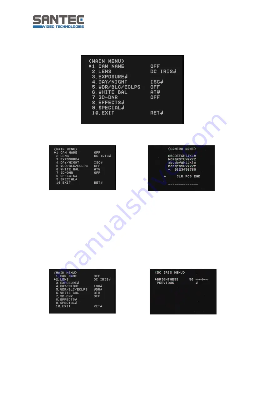
1.  Kamera Name (Cam Name) 


Ein Kameratitel/-name oder eine Kameranummer kann auf dem Bildschirm 
eingeblendet werden. 

Dazu muss „ON“ aktiviert sein. Ein Kamera Name kann aus bis 

zu 15 Zeichen bestehen. 
Wählen Sie durch Bewegung des Joysticks nach rechts/links/oben/unten den 
gewünschten Buchstaben/Zahl aus und bestätigen Sie Ihre Auswahl durch Druck auf 
den Joystick. Gehen dann zum nächsten Buchstaben/Zahl.  
Mit CLR löschen Sie den kompletten Kameratitel. 
Mit POS können Sie die Positionierung der Kameratitel-Einblendung bestimmen.  
Mit END bestätigen Sie den eingegebenen Kameratitel. 


2.  Objektiv (Lens) 


DC Iris: 

Wählen Sie diese Einstellung, wenn ein DC Auto-Objektiv verwendet 
wird. Durch Druck auf den Joystick können Sie die Bildhelligkeit regeln 
(0-100). 


Manual: 

Diese Kamera ist mit einem DC-Objektiv ausgestattet. Es muss daher 
„DC Iris“ eingestellt sein. 

Summary of Contents for VTC-279IRPWD

Page 1: ...0710 dt engl A6 BEDIENUNGSANLEITUNG USER MANUAL DEUTSCH ENGLISH Tag Nacht Kamera im Wetterschutzgeh use Day night camera in weather proof housing Modelle Models VTC 279IRPWD VTC 280IRPWDU VTC 282IRPW...

Page 2: ...video com Impressum Das Copyright dieser Bedienungsanleitung liegt ausschlie lich bei SANYO VIDEO Vertrieb AG Jegliche Vervielf ltigung auch auf elektronischen Datentr gern bedarf der schriftlichen G...

Page 3: ...ideo com All rights reserved This publication may not be reproduced stored in a retrieval system or transmitted in any form or by any means electronic mechanical photocopying recording or otherwise wi...

Page 4: ...sichtsma nahmen 5 2 Allgemeine Sicherheitshinweise 6 3 Installation 8 4 Die Kamera im berblick 10 5 Einstellung der Kamera ber das OSD Bildschirmmen 11 6 Besondere Ausstattungsmerkmale 19 7 Technische...

Page 5: ...ngssymbol weist auf unbedingt zu beachtende Betriebs und Wartungsanweisungen hin CE Richtlinien Vorsicht nderungen und Modifizierungen die nicht ausdr cklich durch die zust ndige Genehmigungsbeh rde g...

Page 6: ...werden Sorgen Sie daf r dass das Ger t nicht berhitzt wird Verwenden Sie nur die empfohlene Betriebsspannungsversorgung Wenn Sie nicht sicher sind ob die am Installationsort vorhandene Stromversorgung...

Page 7: ...f dem Bildschirm das gesamte Bild berstrahlen Dieser Nachzieheffekt ist kein Fehler sondern eine Eigenart der Halbleiter CCD s wenn dieser einer starken Lichtquelle direkt ausgesetzt wird Bei Einsatz...

Page 8: ...m gestellt sein berpr fen Sie den Schalter falls das Videobild schlecht dargestellt ist An der roten Kabelbuchse wird die Stromversorgung angeschlossen Mittelpin au en Die gelbe BNC Buchse ist der Vid...

Page 9: ...Mini Joystick ber ein Bildschirm Men OSD Dr cken Sie oben auf diesen Joystick und es ffnet sich ein Men im Videobild Nun k nnen Sie mit diesem Joystick durch Bewegen des Sticks link rechts oben unten...

Page 10: ...ld 3 Anschl sse VTC 279IRPWD VTC 282IRPWD VTC 280IRPWDU VTC 289IRPWD siehe auch Seite 8 Punkt 3 Betriebsspannung Video Wandhalter mit integriertem Kabelmanagement Objektiveinstellung Regler zur Einste...

Page 11: ...s einen Druck auf den Joystick Wenn Sie auf den Joystick dr cken ffnet sich das folgende Men Men bersicht Kamera Name Cam Name An On Aus Off Objektiv Lens DC Iris Manuell Manual 1 Belichtung Exposure...

Page 12: ...ks nach rechts links oben unten den gew nschten Buchstaben Zahl aus und best tigen Sie Ihre Auswahl durch Druck auf den Joystick Gehen dann zum n chsten Buchstaben Zahl Mit CLR l schen Sie den komplet...

Page 13: ...ie Kamera erkennt automatisch die Lichtverh ltnisse und erstellt ein scharfes Bild Bei aktiviertem Sens up k nnen Sie die Verschlusszeit einstellen x2 x512 Je h her der Wert eingestellt wird desto ehe...

Page 14: ...ein scharfes Bild des Objekts und des Hintergrunds erreicht werden Sie k nnen w hlen zwischen Aus off niedrig low mittel middle und hoch high ECLPS Eclipse Highlight Compensation Durch die Spitzlicht...

Page 15: ...genden F llen nicht einwandfrei funktionieren a wenn die Farbtemperatur um das Objekt herum au erhalb des Bereichs liegt z B bei klarem Himmel oder Sonnenuntergang b wenn die Umgebungsbeleuchtung um d...

Page 16: ...ast Einstellung des Kontrastwerts Sch rfe Sharpness Einstellung der Sch rfe Ein h herer Wert macht das Bild klarer und sch rfer CR Gain Einstellung des Rot Werts CB Gain Einstellung des Blau Werts Ini...

Page 17: ...nglichen Einstellungen werden wieder hergestellt Previous Zur ck zum Hauptmen Privatzonen privacy mask Mask number 8 Bereiche k nnen definiert werden die nicht auf dem Bildschirm angezeigt werden Mas...

Page 18: ...nen Sie LineLock Synchronsation durchf hren Monitor Typ Einstellungen gem Monitor LCD CRT Monitore k nnen verwendet werde Werkseinstellungen Factory Reset Alle Einstellungen werden auf Werkseinstellun...

Page 19: ...CD Aktive Bildelemente 755 H x 582 V Horizontale Aufl sung 650 TVL Minimale Beleuchtung 0 05 Lux 0 0 Lux Signal Rauschabstand 55 dB Gegenlichtkompensation WDR BLC ECLPS Videoausgang 1 0 Vss an 75 Ohm...

Page 20: ...Bedienungsanleitung User Manual VTC 279IRPWD VTC 280IRPWDU VTC 282IRPWD VTC 289IRPWD _________________________________________________________________________________ 20...

Page 21: ...product s enclosure that may be of sufficient magnitude to constitute a risk of electric shock to a person Warning This symbol is intended to alert the user to the presence of important operating and...

Page 22: ...the appliance does not overheat The appliance should only be operated from the type of power source indicated on the marking label If you are not sure of the type of power supplied at the installation...

Page 23: ...e damages Never point the camera at an object with a high degree of luminance Bright vertical or horizontal lines can result in a distortion outshine of the entire image on the monitor This artifact i...

Page 24: ...onitor is connected directly the monitor impedance has to be set to 75 Ohm Verify the position of the switch in case the video picture is of poor quality Power supply is being connected to the red cab...

Page 25: ...es connection is being done by the included adapter The camera adjustments are done by an OSD on screen display menu using a mini joystick Press onto this joystick and a menu pops up in the video pict...

Page 26: ...ents Picture 3 Connections VTC 279IRPWD VTC 282IRPWD VTC 280IRPWDU VTC 289IRPWD also see page 8 item 3 Power supply Video wall bracket with integrated cable management lens adjustment via setting ring...

Page 27: ...choice press onto the joystick In case the menu says SET key this means pressing the joystick If you press the joystick the following menu overview pops up Menu overview Cam Name On Off Lens DC Iris M...

Page 28: ...er Confirm your choice by pressing the joystick Then go to the next letter number You can use the arrows and to move forward or backward in the camera title if you wish to make corrections CLR Delete...

Page 29: ...s controlled manually 1 160 1 90000 x2 x512 Sens up The camera automatically detect the light level and creates a clear picture You can adjust the shutter speed x2 x512 The higher the value the more l...

Page 30: ...C Backlight Compensation If the object is exposed to strong backlight you can activate the backlight function in order to achieve a clear picture of both the object itself and the background You can s...

Page 31: ...ork properly under the following conditions a If the colour temperature surrounding the object is our of the control range e g clear sky or sunset b If the ambient illumination around the object is di...

Page 32: ...contrast level Sharpness Adjust the sharpness level By increasing the value the picture becomes strong and clear CR Gain Adjust the red colour portion in the video CB Gain Adjust the blue colour port...

Page 33: ...nsitivity Initial set Return to default settings Previous Return to main menu Privacy mask Mask number 8 privacy zones can be defined which are hidden on the screen Mask state Determine the privacy zo...

Page 34: ...n iss et to internal If you use 24 V AC at 60 Hz you can also use LineLock synchronsation Monitor type Change the settings according to your monitor LCD CRT monitors can be used Factory Reset Return t...

Page 35: ...Sensor 1 3 Sony CCD Pixel 755 H x 582 V Horizontal resolution 650 TVL Min illumination 0 05 lux 0 0 lux S N ratio 55 dB Backlight compensation WDR BLC ECLPS Video output 1 0 Vpp at 75 Ohm BNC connecto...

Page 36: ...__________________________________________________________________________ www santec video com Ihr Fachh ndler Your local distributor...

Reviews: