COMPUTER REAR PANEL
PC / LINUX / MAC
Giga LAN
NETWORK SWITCH PEAR PANEL
/ B
HARDWARE INFORMATION
PACKAGE CONTENTS
/ B / XE / BXE
Power Cord
Manual / CD
USB 2.0 Cable
eSATA Cable
SATA Backet
HD Tray Keys
Removable Tray Modules (Screws Included)
NOTE:
Please contact Sans Digital in case of missing or damaged items.
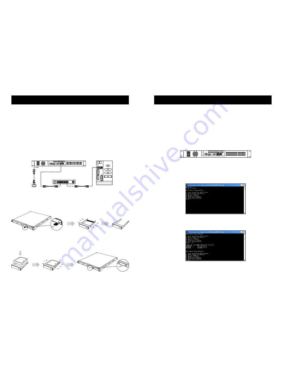
HAREWARE CONNECTION DIAGRAM
HARD DRIVE INSTALLATION
Step-1:
Press the key into the lock slot (located on front of each hard drive tray), until tray
handle releases. Pull the tray handle to remove the tray from the enclosure. Dismount the
plastic tray protectors by removing the screws in the illustration below.
Step-2:
Place the hard drive into the tray, and fasten the screws in the corresponding loca-
tions. Place the tray with the mounted hard drive back into the enclosure. (If the screws are
not properly fastened, the hard drive may be pushed towards the back of the unit and the
tray handle will not open properly.)
.................................................................... 1
............................................................................................................................................... 1
............................................................................................................................................... 1
............................................................................................................................................ 1
.............................................................................................................................................. 1
.............................................................................................................................................. 1
............................................................................................................................................. 1
....................................................................................... 4
INTEGRATION AND SETUP
DEFAULT SETTINGS:
LAN Port#1 IP address:
DHCP
Administrator Username:
root
Password:
0000
(4 zeros)
INITIAL SETUP – Assigning IP to the Unit
1.
Connect the NAS unit to your network (connect the RJ45 network cable to the LAN
port 1 as shown in the diagram below), power the unit on and allow it approximately
two (2) minutes to boot up.
2.
Go to a computer that connected to the same network as the NAS unit. Insert the
included (B) CD into the CD-ROM drive of the computer. Copy the “NAS-
Finder.exe” to the computer and run “NAS-Finder.exe” to locate the NAS unit. This
software will allow you to assign an IP address to the NAS unit.
3.
After executing the NAS-FINDER program, a DOS dialog box will appear with the
main menu.
4.
To view client (NAS unit) information, typing ‘2’ within the main menu and press
‘enter’. The dialog box will display each detected NAS unit along with their network
settings. A number is assigned to each detected unit, starting from #1. In the example
below, Client #1, (B) is detected, with IP address 192.168.0.93.
NOTE:
Information, such as MAC address, IP address, NETMASK and etc, may be
different from system to system.
5
6


