background image

4.  Set the control switch to the 

“CLEANOUT” 

position 

and agitate for approximately 1


- 2 minutes and then 

drain the water by opening the spigot. After the unit is 
empty, set the control switch to the 

“OFF” 

position. 

 
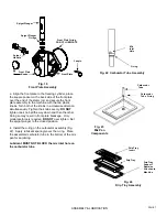
5.  Remove the front plate by turning the black plastic 
knobs in a counterclockwise direction (Fig. 5). 
Disassemble the front plate in the following manner: 

DO NOT USE ANY TOOLS OR SHARP OBJECTS TO 
REMOVE ANY O-RINGS FROM THIS MACHINE. 
SHARP OBJECTS WILL DAMAGE THE O-RINGS. 
 

a.    Remove the faspin and spigot handle. 
b.    Remove the front plate o-ring. 
c.    With the spigot handle removed, push the spigot 
 

plunger out the top of the front plate. 

d.    Remove the o-rings from the spigot plunger by 
 

grasping the part with one hand and with a dry 


cloth in the other hand, squeeze the o-ring upward. 


When a loop is formed, grasp the o-ring with the 


other hand and roll it out of its groove and off the 


part (Fig. 6). 


6.  Remove the carburetor tube (Fig. 7) from the mix 
pan. Disassemble and clean in the following manner: 
 
a.    Remove the o-ring from the bottom of the tube. 
b.    Clean the inside of the tube with the brush. 


7.  Remove the dasher assembly (Fig. 8) being careful 
 

not to damage the scraper blades, then disassemble 


in the following manner: 

a.    Remove and take apart the rear seal assembly. 
b.    Remove the stator rod from the dasher. 

C.    

Remove the blade from the dasher (Fig. 9a) 


by first rotating blade upward (Fig. 9b) and then 


unsnapping one end from the support rod. 


BLADES MUST BE REMOVED FOR CLEANING. 

IMPORTANT 

DISASSEMBLY & CLEANING 

Fig. 5 

Face Plate Assembly


Spigot Plunger


Faspin


Spigot  
Handle


Front Plate


Front Plate O-ring 

DO NOT LUBRICATE


Spigot Plunger  

O-rings 

Front Plate 

Knobs


Fig. 6 

O-Ring Removal


Fig. 7 

Carburetor Tube  

PAGE  3 

O-ring 

Mix  

Inlet 

Hole 

Summary of Contents for DF200

Page 1: ... Reliability from the team that Serves the Best Operation Manual DF200 Soft Serve Dispenser SaniServ P O Box 1089 Mooresville Indiana 46158 SaniServ An AFFINIS GROUP Company ...

Page 2: ...facility 2 This warranty applies only to the original purchaser at the original installation location and is only good if the purchaser has returned the fully completed the product registration form to SaniServ within ten 10 days of the date of purchase by the original purchaser user but not to exceed eighteen 18 months from date of shipment from factory 3 Warranty labor coverage at SaniServ s sta...

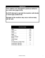
Page 3: ...ght lb kg 172 78 115 Volt 60 Cycle Single Phase Circuit Amps Minimum 11 Circuit Amps Maximum 11 SPECIFICATIONS This machine was designed to produce softserve ice cream and yogurt only Do NOT attempt to operate this machine with shake or slush type product mix Damage to the machine may occur and warranty will be void IMPORTANT ii ...

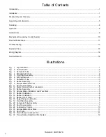
Page 4: ...sembly 3 Fig 6 O Ring Removal 3 Fig 7 Carburetor Tube 3 Fig 8 Dasher Assembly 3 Fig 9 Scraper Blade Removal 4 Fig 11 Drip Tray Assembly 4 Fig 12 Stator Rod and Dasher Lubrication 5 Fig 13 Dasher Assembly 5 Fig 14 Scraper Blade Installation and Wear Mark 5 Fig 15 Dasher Installation 6 Fig 16 Dasher Installation 6 Fig 17 Dasher Front View 6 Fig 18 Spigot Plunger Lubrication 6 Fig 19 Front Plate Asse...

Page 5: ...INE DATA PLATE SPECIFICATIONS ALWAYS SUPERSEDE ELECTRICAL INFORMATION IN THIS MANUAL FAILURE TO PROVIDE FOR PROPER EARTH GROUND ACCORDING TO LOCAL APPLICABLE ELECTRICAL CODES COULD RESULT IN SERIOUS ELECTRICAL SHOCK OR DEATH DO NOT USE EXTENSION CORDS DO NOT TURN MACHINE ON Introduction Installation Fig 1 Leg Installation Minimum Clearance 4 Counter Top Models WARNING IMPORTANT This manual provide...

Page 6: ...y and drain the water by pulling downward on the spigot handle After the machine is empty set the control switch to the OFF position Repeat the above procedure as necessary to make certain that all product is removed from the machine 2 Prepare a suitable detergent and water solution at a temperature of 125 to 130 F DO NOT use an abrasive detergent on any part of the dispenser DO NOT USE HOT WATER ...

Page 7: ...eze the o ring upward When a loop is formed grasp the o ring with the other hand and roll it out of its groove and off the part Fig 6 6 Remove the carburetor tube Fig 7 from the mix pan Disassemble and clean in the following manner a Remove the o ring from the bottom of the tube b Clean the inside of the tube with the brush 7 Remove the dasher assembly Fig 8 being careful not to damage the scraper...

Page 8: ...r five 5 minutes and then air dry to prepare for assembly and lubrication DO NOT wipe dry 12 The remainder of the machine including the mix pan and freezing cylinder must be cleaned in place using a mild detergent solution Clean the exterior with a damp cloth DO NOT use an abrasive cleaner on exterior panels WHEN CLEANING THE MACHINE DO NOT ALLOW EXCESSIVE AMOUNTS OF WATER AROUND ANY ELECTRICALLY ...

Page 9: ...rection as viewed from the front of the dasher Fig 14b Note Reverse the blades at each cleaning to maintain sharpness In addition the blades are equipped with a wear mark Fig 14c When the blade is worn to this wear mark they must be replaced Assembly Lubrication Use only food approved lubricants Sanigel SaniServ part number 188490 is recommended and is available from your local authorized SaniServ...

Page 10: ...de the cylinder Scraper blades should be visible Fig 17 extending approximately 1 8 beyond the dasher CORRECT Fig 17 Dasher with Blade Front View 2 Lubricate and assemble the front plate assembly in the following manner a Install the two o rings on the spigot plunger by rolling them onto the plunger Seat the o rings in the grooves Make certain that they are not twisted Smooth the lubricant into th...

Page 11: ...OT over tighten Set the spigot plunger to the closed position 4 Install the o ring on the carburetor assembly Fig 22 Apply lubricant sparingly over the o ring Place the assembled carburetor tube in the bottom of the mix pan for sanitizing Lubricant MUST NOT BLOCK the mix inlet hole on the carburetor tube ASSEMBLY LUBRICATION Spigot Plunger Faspin Spigot Handle Front Plate Front Plate O ring DO NOT...

Page 12: ...1 Remove the carburetor tube from the bottom of the mix pan and set aside in a sanitary location 2 Install the drip tray and drip tray insert 3 Place a 16 oz Cup under the spigot and open the spigot handle Pour approximately one quart of fresh product mix into the mix pan This will chase the sanitizing solution from the mix pan and freezing cylinder Close the spigot handle when the sanitizer is pu...

Page 13: ...tart of each day Drip Tray This should be removed daily and cleaned to remove residue Mix Pan Lid Be certain to leave the lid in place on top of the machine to prevent any foreign materials from contaminating the mix Mixing Make certain that the product mix is prepared according to label instructions Sanitizing Do not soak plastic parts in sanitizer overnight Doing so can cause the plastic parts t...

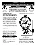
Page 14: ...side of the machine marked Do Not Adjust EXTREME CARE SHOULD BE EXERCISED TO KEEP HANDS AND TOOLS AWAY FROM MOVING PARTS PERSONAL INJURY COULD RESULT 3 Replace panels restore power wait until the compressor cycles off then check the consistency of the product 4 Repeat steps 2 and 3 until the desired product consistency is obtained Consistency Adjustment CAUTION The following procedure should ONLY ...

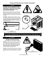
Page 15: ...and clean all parts inside of the machine including the base side panels fan blades condensers etc Fig 31 Drip Chute DISCONNECT THE MACHINE FROM ITS POWER SOURCE S BEFORE PERFORMING ANY ROUTINE MAINTENANCE PERSONAL INJURY OR DAMAGE TO THE MACHINE COULD RESULT IF THIS PRACTICE IS NOT OBSERVED Daily Inspect the machine for signs of product leaks past seals and gaskets If proper assembly does not sto...

Page 16: ...ve surface with a fine grade of emery cloth and apply anti seize compound 7 Reinstall the belt idler arm DO NOT OVERTIGHTEN THE LOCKING NUT ON SOME UNITS IT IS POSSIBLE TO OVERTIGHTEN THE LOCKING NUT AND CAUSE THE IDLER ARMS TO BIND THE ARMS SHOULD MOVE FREELY 8 Repeat the process for the torque idler arm 9 Install the belt making certain that there is no grease on the belt or pulleys Step to the ...

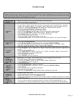
Page 17: ...r rod Check dasher assemblies Check for sticking spigot lever and or switch If stuck in the up position will cause unit to run continually Front Plate Leaking Confirm front plate o ring is not ripped or torn Replace if necessary Replace seals and o rings every six months Do not lubricate front plate o ring Confirm spigot plunger o rings are not ripped or torn Replace if necessary Replace every six...

Page 18: ...t On gravity fed freezers the front plate indirectly holds the dasher in place via the stator rod It also provides compression for the rear seal Freezing Cylinder The part of the refrigeration mechanism in which the refrigerant vaporizes and absorbs heat This is the part of the freezer where the liquid product is frozen Mix pan Is the top container that product is poured into It is used as storage...

Page 19: ... starved cylinder is often mistaken for a freeze up or product too thick A starved cylinder starving is created when a larger percentage of frozen product is dispensed from the freezing cylinder than the percentage of liquid product entering the freezing cylinder from the mix pan There are several causes of starving 1 Overdrawing Dispensing more product from the machine than it s designed to do Th...

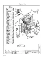
Page 20: ...Exploded View PAGE 16 ...

Page 21: ...Wiring Diagram PAGE 17 ...

Page 22: ...Date Service Performed Serviceman s Signature Service Record SERVICE RECORD ...

Page 23: ...This Page Intentionally Blank ...

Page 24: ...dly made in the U S A Technical Publication Publ No 80856 Updated 4 06 451 E County Line Road P O Box 1089 Mooresville Indiana 46158 5089 SaniServ An AFFINIS GROUP Company We are on the web www saniserv com ...

Reviews: