Installer’s Preoperational Check
THE FOLLOWING ITEMS MUST BE PERFORMED BEFORE ATTEMPTING TO OPERATE THE EQUIPMENT:
INSTALLERS PREOPERATIONAL CHECK
PAGE 2
WARNING! HAZARDOUS MOVING PARTS. DO
NOT WEAR LOOSE FITTING CLOTHING. KEEP
HANDS, HAIR, AND CLOTHING AWAY FROM
MOVING INTERNAL PARTS.
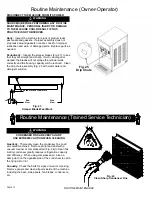
1. Remove the front plate (Fig. 1) by turning the black
plastic knobs in a counterclockwise direction.
After removing the knobs, pull the front plate off the
studs. Then grasp the front of the dasher assembly
(Fig.3) and remove it from the dispenser by pulling
it out slowly and straight so the scraper blades are
not damaged.
2. Set the Auto/Clean switch (Fig. 2) to the
“AUTO”
position. Doing so allows the compressor and
dasher motor to start. Check to see that the
refrigeration system is operating by feeling the
inside of the freezing cylinder.
It should turn cold
within one minute.
3. Set the Auto/Clean switch to the
“OFF”
position.
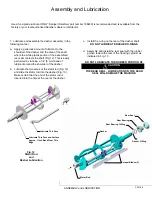
4. Install
the
Dasher Assembly
(Fig. 3) inserting it in
the freezing cylinder and pushing toward the rear of
the cylinder while rotating the assembly until it seats
into the drive at the rear of the cylinder.
5. Install
Front Plate Assembly
and secure with the
black knobs (Fig. 1).
UNDER NO CIRCUMSTANCES SHOULD THE UNIT
BE OPERATED IN THE “AUTO” POSITION FOR
MORE THAN THREE MINUTES WITH EMPTY
FREEZING CYLINDERS . DOING SO WILL RESULT
IN DAMAGE TO THE MACHINE
CAUTION
BEFORE PROCEEDING TO STEP 2, BE CERTAIN
THAT THE DASHER HAS BEEN REMOVED
WARNING
Rear Seal
Rear Bearing
Dasher O-Ring
Rear Bearing O-Ring
Scraper
Dasher
Stator Rod
Fig. 2
Auto/Clean Switch
CLEANOUT
AUTO
OF
F
OF
F
Fig. 3
Dasher Assembly
Fig. 1
Front Plate
Summary of Contents for A7081HEP
Page 2: ......
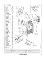
Page 17: ...PAGE 16 ASSEMBLY DIAGRAM ...
Page 18: ...Notes ...
Page 19: ...Service Log ...


