Installation & Operation Manual Merlin GDPX+
GDPXPLUS - IOM Iss: 8 02-21
5
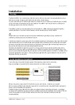
Fixing
Unpack all the parts!
Designed for surface mounting, it must be installed by a licensed, insured contractor.
1.
Carefully remove the front cover from the unit by
unscrewing the four bolts located at each corner. To do
this – use the socket wrench provided.
2.
Mark the four screw holes located on the back of the
enclosure to the wall. Ensure the wall surface is flat to
prevent base distortion.
3.
After executing the mounting and the connections –
replace the front cover and insert the security caps over
the four bolts.
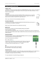
Board Connections Diagram
Be careful when creating access for cables – Damage to boards will void any warranty!
Any damage attempting to remove the circuit board parts may void any warranty!
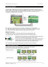
Wiring of different circuits shall be separated by means of routing, clamping or barrier!
All Class 2 wiring is to be installed within flexible tubing to maintain segregation between circuits!
For MODBUS communications, a shielded cable is used!


