


100
10(17)
15(25.5)
20(34)
25(42.5)
30(51)
35(59.5)
40(68)
90
80
70
60
50
40
30
20
10
0
0
4
8
12
16
20
24
28
32
36
40
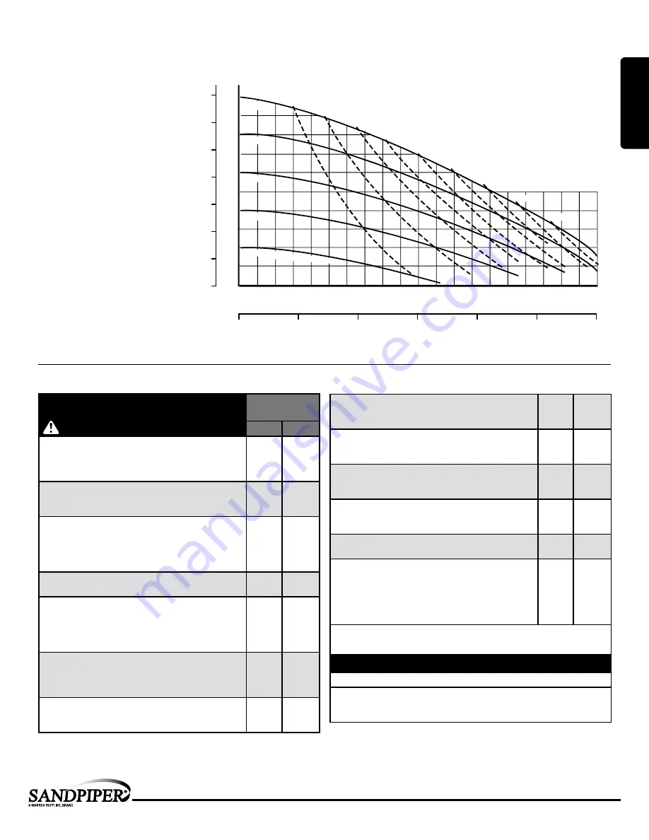
100 PSI
80 PSI
60 PSI
40 PSI
20 PSI Air Inlet Pressure
0
50
75
100
125
150
BAR
25
0
1
2
3
4
5
6
7
PSI
45(76.5)
50(85)
Liters per minute
U.S. Gallons per minute
CAPACITY
AIR CONSUMPTION
SCFM (M
3
/hr)
HEAD
MODEL SB1/SB25 Performance Curve
Performance based on the following: elastomer fitted pump, flooded suction,
water at ambient conditions. The use of other materials and varying hydraulic
conditions may result in deviations in excess of 5%.
sb1dl5sm-rev0317
sandpiperpump
.
com
Model SB1 & SB25 •
2
Performance
SB1 & SB25
SUCTION/DISCHARGE PORT SIZE
• SB1: 1” (25.4mm) NPT(F)
• SB25: 1” (25.4mm) BSP Tapered
CAPACITY
• 0 to 42 gallons per minute
(0 to 159 liters per minute)
AIR DISTRIBUTION VALVE
• No-lube, no-stall design
SOLIDS-HANDLING
• Up to nearly .25 in. (6.3mm)
HEADS UP TO
• 125 psi or 289 ft. of water
(8.8 Kg/cm
2
or 88 meters)
MAXIMUM OPERATING PRESSURE
• 125 psi (8.6 bar)
DISPLACEMENT/STROKE
• .09 Gallon / .34 liter
SHIPPING WEIGHT
• Aluminum 31 lbs. (14kg)
• Stainless Steel 45 lbs. (20kg)
• Alloy C 45 lbs. (20kg)
• Stainless Steel with Cast Iron Center 65 lbs. (30kg)
• Alloy C with Cast Iron Center 65 lbs. (30kg)
Materials
Material Profile:
Operating
Temperatures:
Max.
Min.
Conductive Acetal:
Tough, impact resistant, ductile. Good
abrasion resistance and low friction surface. Generally inert, with
good chemical resistance except for strong acids and oxidizing
agents.
190
°
F
88
°
C
-20
°
F
-29
°
C
EPDM:
Shows very good water and chemical resistance. Has
poor resistance to oils and solvents, but is fair in ketones and
alcohols.
280
°
F
138
°
C
-40
°
F
-40
°
C
FKM:
(Fluorocarbon) Shows good resistance to a wide range
of oils and solvents; especially all aliphatic, aromatic and
halogenated hydrocarbons, acids, animal and vegetable oils.
Hot water or hot aqueous solutions (over 70
°
F(21
°
C)) will
attack FKM.
350
°
F
177
°
C
-40
°
F
-40
°
C
Hytrel®:
Good on acids, bases, amines and glycols at room
temperatures only.
220
°
F
104
°
C
-20
°
F
-29
°
C
Neoprene:
All purpose. Resistance to vegetable oils. Generally
not affected by moderate chemicals, fats, greases and many
oils and solvents. Generally attacked by strong oxidizing acids,
ketones, esters and nitro hydrocarbons and chlorinated aromatic
hydrocarbons.
200
°
F
93
°
C
-10
°
F
-23
°
C
Nitrile:
General purpose, oil-resistant. Shows good solvent, oil,
water and hydraulic fluid resistance. Should not be used with
highly polar solvents like acetone and MEK, ozone, chlorinated
hydrocarbons and nitro hydrocarbons.
190
°
F
88
°
C
-10
°
F
-23
°
C
Nylon:
6/6 High strength and toughness over a wide
temperature range. Moderate to good resistance to fuels, oils
and chemicals.
180
°
F
82
°
C
32
°
F
0
°
C
Polypropylene:
A thermoplastic polymer. Moderate tensile
and flex strength. Resists stong acids and alkali. Attacked by
chlorine, fuming nitric acid and other strong oxidizing agents.
180
°
F
82
°
C
32
°
F
0
°
C
PVDF:
(Polyvinylidene Fluoride) A durable fluoroplastic with
excellent chemical resistance. Excellent for UV applications.
High tensile strength and impact resistance.
250
°
F
121
°
C
0
°
F
-18
°
C
Santoprene®:
Injection molded thermoplastic elastomer with
no fabric layer. Long mechanical flex life. Excellent abrasion
resistance.
275
°
F
135
°
C
-40
°
F
-40
°
C
UHMW PE:
A thermoplastic that is highly resistant to a broad
range of chemicals. Exhibits outstanding abrasion and impact
resistance, along with environmental stress-cracking resistance.
180
°
F
82
°
C
-35
°
F
-37
°
C
Urethane:
Shows good resistance to abrasives. Has poor
resistance to most solvents and oils.
150
°
F
66
°
C
32
°
F
0
°
C
Virgin PTFE:
(PFA/TFE) Chemically inert, virtually impervious.
Very few chemicals are known to chemically react with PTFE;
molten alkali metals, turbulent liquid or gaseous fluorine and
a few fluoro-chemicals such as chlorine trifluoride or oxygen
difluoride which readily liberate free fluorine at elevated
temperatures.
220
°
F
104
°
C
-35
°
F
-37
°
C
Maximum and Minimum Temperatures are the limits for which these materials can be operated.
Temperatures coupled with pressure affect the longevity of diaphragm pump components.
Maximum life should not be expected at the extreme limits of the temperature ranges.
Metals:
Alloy C:
Equal to ASTM494 CW-12M-1 specification for nickel and nickel alloy.
Stainless Steel:
Equal to or exceeding ASTM specification A743 CF-8M for corrosion
resistant iron chromium, iron chromium nickel and nickel based alloy castings for
general applications. Commonly referred to as 316 Stainless Steel in the pump industry.
For specific applications, always consult the Chemical Resistance Chart.
CAUTION!
Operating temperature limitations are as follows:
Ambient temperature range:
-20°C to +40°C
Process temperature range:
-20°C to +80°C for models rated as category 1 equipment
-20°C to +100°C for models rated as category 2 equipment
In addition, the ambient temperature range and the process temperature range do not exceed the operating temperature range of the applied non-metallic parts as listed in the manuals of the pumps.
ATEX Detail
MODEL SPECIFIC
UNIVERSAL ALL AODD
1: PUMP
SPECS


