background image


17 


3700 Osuna Road NE 
Suite 711 
Albuquerque, NM 87109 
www.sandia.aero 

3.7


Cold Temperature Startup 

At operating temperatures below 10° C, the battery pack requires a pre-heating cycle prior to 
being brought on-line.  The heating time period will depend on the ambient temperature and will 
range from a few moments to up to a maximum of 15 minutes (cold-soaked at -20°C). 

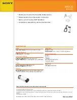
During the battery heating cycle, the BAT HEATING message is shown in red and the battery 
icon is Red-X’ed, indicating battery operation is currently not supported: 


Figure 21 - Battery Heating Message 


While the battery is heating, operation from battery power is inhibited.   

Loss of power will result in the unit shutting down. 

Prior to departure or entry into IFR conditions, verify that the battery is NOT in a 

heating cycle. 


3.8


Sensor Failure 

If any internal sensor fails, the corresponding parameter on the display will remain in the Red-
X’ed state.  If this occurs, the unit must be returned to the factory for service.


3.9


Emergency Shutdown Procedure 

In the event that the unit requires shutdown in-flight due to improper operation or other failure 
mode, perform the following sequence: 

1.


Remove power from the unit by opening the corresponding circuit breaker. 

2.


Push and hold the rotary knob for several seconds - this will initiate a manual power-
down sequence. 

3.


Do not cancel the power-down timer – when the timer expires, the unit will internally 
disable the battery and the unit will shut down. 

Re-applying external power to the unit will turn the unit back on. 


Summary of Contents for SAI-340

Page 1: ...3700 Osuna Road NE Suite 711 Albuquerque NM 87109 www sandia aero 306184 00 Rev 3 SAI 340 Pilot Guide...

Page 2: ...is subject to change without prior notice Copyright 2016 SANDIA aerospace Corporation all right rights reserved Printed in USA Record Of Revision Revision Date Description Approval 1 ER 5 19 2015 Init...

Page 3: ...Under Speed Indications 8 2 6 Barometric Altitude 9 2 6 1 Baro Adjustment 9 2 6 2 Default Baro 9 2 7 Instantaneous Vertical Speed Indication IVSI 9 2 8 Altitude Bug 10 2 9 Roll Pitch 10 2 10 Slip Ind...

Page 4: ...escription The SAI 340 Attitude Indicator is a panel mounted attitude airspeed altitude vertical speed and slip instrument The instrument is self contained and directly incorporates all of the sensors...

Page 5: ...de Trim Configuration of Airspeed Units Configuration of V Speeds Configuration of Baro Units Configuration of Baro Default Value Configuration of Battery Type IVSI Filter Lag 1 2 2 System Interfaces...

Page 6: ...ow 0 Figure 2 Power On Screen 2 2 Thermal Stabilization On initial power on the various internal sensors must thermally stabilize While this is occurring the corresponding indicator area will be cover...

Page 7: ...e following message will be presented on the screen Figure 4 Aligning Message 2 4 Pilot Display and Controls The following shows the on screen functions and pilot controls once the system has stabiliz...

Page 8: ...Brightness Align n a Altitude Bug On Increase Decrease Altitude Bug Table 1 Rotary Knob Controls 2 5 Indicated Airspeed Indicated Airspeed is shown on the left side tape and drum Airspeeds between 30...

Page 9: ...nder Speed Indications If operation occurs between Vno and Vne the white surround around the numerical readout will turn amber If operation occurs over Vne or below Vso the surround will turn red Figu...

Page 10: ...InHg or 1013 Mb AUTO will utilize the airport elevation on the last power down to estimate a current baro setting LAST will retain the last pilot entered value The default baro behavior adjustable to...

Page 11: ...e bug a short press of the pushbutton will set the bug Figure 10 c If the altitude bug is not adjusted for 7 seconds while in the editing mode the bug will become set at the current value While editin...

Page 12: ...t and right stops represent 7 degrees If the internal slip sensor fails the area will be Red X ed Figure 12 Slip Indicator 2 11 Brightness Adjustment The screens brightness is either manually or autom...

Page 13: ...Backlight Adjust Menu After displaying the brightness menu pushing the rotary knob again without rotating the knob will leave the unit in the previous operating mode automatic or manual Once placed in...

Page 14: ...Alignment In certain abnormal operations such as aerobics a manual attitude alignment may be required Attitude roll pitch alignment may be performed by momentarily pressing the rotary knob to present...

Page 15: ...the screen Figure 17 Cross Check Message Cross Check may occur during extended periods of extreme turbulence or maneuvering Reestablishing straight and level flight allows the unit to reacquire TSO c...

Page 16: ...y drains Charge levels above 50 are shown in green between 25 and 50 is shown in amber and levels below 25 are shown in red The charge is also shown numerically in percent Figure 19 Charge Status Icon...

Page 17: ...ttery Duration Battery duration is dependent on several factors including age of the battery pack display intensity setting and ambient operating temperature With a healthy battery a minimum of 30 min...

Page 18: ...n the unit shutting down Prior to departure or entry into IFR conditions verify that the battery is NOT in a heating cycle 3 8 Sensor Failure If any internal sensor fails the corresponding parameter o...

Page 19: ...28 00 inHg Minimum operational duration on battery 30 Minutes Maximum roll rate 400 degrees second Maximum operating G force 6 G Battery operation may be inhibited for up to 15 minutes during cold sta...

Page 20: ...sandia aero NOTE Approximately nine percent of the population has some sort of color vision deficiency what is commonly called color blindness It should also be noted that the FAA does not test for a...

Reviews: