background image

100

50

0

[%]

3

0

1200

600

0

[L/h]

Air

1200

600

0

[L/h]

Air

100

50

0

[%]

3

0

1200

600

0

[L/h]

Air

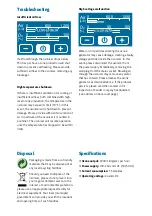
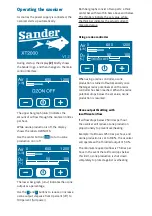
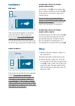
Operating the ozonizer

As soon as the power supply is connected, the 
ozonizer starts up automatically.

During startup, the display 

(2)

 briefly shows 

the Sander logo, and then changes to the main 
control interface:

The upper bar graph (»Air«) indicates the 
amount of airflow through the ozonizer in litres 
per hour.

While ozone production is off, the display 
shows the label »OZON OFF«.

Use the center button (

 I/O 

) to turn ozone 

production on or off.

The lower bar graph (»O3«) indicates the ozone 
output as a percentage.

Use the 

 – 

 and 

 + 

 buttons to reduce or increase 

ozone output stepwise from 0 percent (off) to 
100 percent (full power).

Both bar graphs consist of two parts: a thick 
center bar with two thin bars above and below. 
The thin bars indicate the set value, while 
the thick bar indicates the actual (current) 
measured value.

Using a redox controller

When using a redox controller, ozone 
production is turned off automatically once 
the target redox potential set on the redox 
controller has been reached. When the redox 
potential drops below the set value, ozone 
production is resumed.

Ozone output throttling with 
insufficient airflow

If airflow drops below 250 litres per hour, 
the ozonizer will reduce ozone production 
proportionally to prevent overheating.  

Example: If airflow is 125 litres per hour, and 
ozone production is set to 100 %, the ozonizer 
will operate with a throttled output of 50 %. 

The minimum required airflow is 75 litres per 
hour. In the event that airflow drops below 
this limit, ozone production is shut down 
completely to protect against overheating.

Summary of Contents for XT2000

Page 1: ...Ozonizer XT2000 User Guide EN...

Page 2: ...y cause damage creating a faulty voltage potential inside the ozonizer In this event please disconnect the ozonizer from the power supply immediately removing the wall plug from the mains socket Blowi...

Page 3: ...nnector 7 Disconnect the tubing for inlet air and ozone Remove the screws 4 holding the ozone generator cover 5 in place using the supplied hex tip tool Remove the ozone generator cover 5 Wipe the ozo...

Page 4: ...nsist of two parts a thick center bar with two thin bars above and below The thin bars indicate the set value while the thick bar indicates the actual current measured value Using a redox controller W...

Page 5: ...in combination with a redox controller Sander redox potential detector and controller part number 7 1C This device automatically turns the ozonizer on or off depending on a set value for the redox po...

Page 6: ...rews for the ozone generator cover 5 Ozone generator cover 6 Ozone outlet connector for 6 8 mm tubing 7 3 pin connector for power supply 24 volts 8 4 pin connector for Sander Redox Controller with dum...

Page 7: ...x Controller Hex tip Allen tool Mounting hooks 2 Mounting dowels 2 User guide Intended use for aquariums and ponds The ozonizer is a device for generating ozone from air It was developed speci cally f...

Page 8: ...nce and cleansing tasks may be performed by children only under supervision Do not open the ozonizer s casing Improper repair work or other modi cations may create considerable hazards In the event th...

Page 9: ...9 to an air pump using 6 8 mm tubing Connect the ozone outlet 6 to the airstone in the skimmer using ozone resistant tubing If ozone production is turned off while the ozonizer is still connected to t...

Page 10: ...e Eltze Germany Phone 49 51 73 9 71 0 Fax 49 51 73 9 71 197 E mail info aqua sander de Web www aqua sander de 2 2018 Erwin Sander Elektroapparatebau GmbH Design ngin de For more information expert adv...

Reviews: