S&C Instruction Sheet 1076-510 7
Installation
Before Starting Installation
This instruction sheet provides an overview of the
SpeedNet Cell Edge Gateway. Choose a location where the
SpeedNet Cell Edge Gateway can be securely mounted.
NOTICE
For remote antenna installation, where the antenna
is not mounted directly on the control enclosure, S&C
recommends installing lightning protection.
Network Design
SpeedNet Cell Edge Gateways can be installed in a variety
of network configurations. Plan your network in advance
and develop a logical Internet Protocol (IP) addressing
scheme for your particular application.
SIM Card Installation
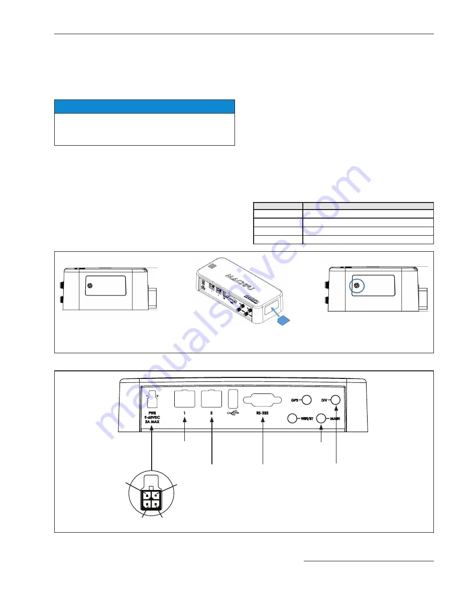
Open the SIM card access door and insert the micro-SIM
card in the SIM-card slot. See Figure 1.
Cable Installation
Follow these steps for proper cable connection:
STEP 1.
Connect the antenna to the SpeedNet Cell Edge
Gateway.
STEP 2.
Connect an Ethernet cable to the SpeedNet Cell
Edge Gateway and personal computer (PC)
used for configuring the gateway.
STEP 3.
Connect a power supply to the SpeedNet Cell
Edge Gateway.
Connections and LED Indicator Lamps
The front panel of the SpeedNet Cell Edge Gateway has
connectors for cellular antennas (main and diversity), the
12-Vdc power supply plug, the RS-232 serial port, and two
Ethernet ports. See Figure 2.
Table 1.
Connector
Description
Cellular antenna
Main and Diversity SMA connectors
Power
9- to 60-Vdc input, 4-pin Microfit 3.0 connector
Serial
RS-232 Sub-D 9-pin (DTE) serial port
Ethernet
10/100 Base-T RJ45 Ethernet ports
Figure 2. SpeedNet Cell Edge Gateway front panel.
Ethernet 1
Cellular
(Main)
Ethernet 2
RS-232
(DTE)
Cellular
(Diversity)
Switch in -
Power
Switch in +
GND
Figure 1. SIM Card Installation.
Slide SIM card into holder through opening and
push until latch clicks. To remove push again
until latch disengages, and slide SIM card out.
Unscrew and remove SIM door.
Replace and screw in SIM door.


