28 S&C Instruction Sheet 765-510
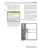
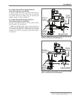
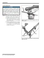
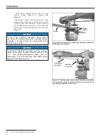
Figure 31. The blade and contact assembly in the fully
Closed position.
Blade
Guide fingers
Checking Operation
NOTICE
If furnished with provisions for power operation
using the 6801M Automatic Switch Operator (catalog
number suffix “-M”), perform Steps 21 and 22 using
the installed 6801M operator and the instructions
described in the "Adjusting the Tap Position on
the Load Resistor" section of the 6801M Operator
installation instructions (S&C Instruction Sheet
1045M-510).
STEP 21.
Open and close the interrupter switch by
swinging the handle slowly through its full
travel. Make sure the following conditions exist:
(a) With the operating handle as far as it will go
in the closing direction, all main contacts of
the interrupter switch are in the fully
Closed
position. See Figure 31.
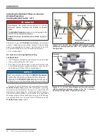
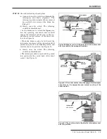
(b) With the operating handle as far as it will go
in the opening direction, the switch blades
are 90 degrees from the
Closed
position
(perpendicular to the switch mounting-
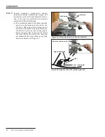
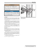
weldment). See Figure 32.
Figure 32. The blade at the 90 degrees from switch mounting-
weldment position.
Switch mounting-
weldment
Blade
Installation


