20 S&C Instruction Sheet 1023-550
Using IntelliLink Software to Locate Problems
High/Low Voltage Band
This field displays “Active” when the Bank Voltage Margin average value is greater
than the difference between the
High-Voltage Override Value
setpoint and the
Low-
Voltage Override Value
setpoint for the present season. See Page 1 of the
Setup>General
screen for more information.
Reset NS Lockout
If the control is locked out because of a neutral sensor error, this field lets you clear the
lockout. If the condition persists, the alarm reappears. The
Neutral-Sensor Lockout
condition will also be reset, and the associated neutral alarms cleared, whenever the
control changes operating modes, either from
Manual
to
Automatic
mode or from
Automatic
to
Manual
mode. When the neutral condition is still present: in
Manual
mode
the control will lockout again and in
Automatic
mode it will attempt
Corrective Action
and
Retry
, if these features are enabled.
Reset Alarms Request
The
Reset All Alarms
request attempts to clear all trouble and error conditions. When the
condition persists, the alarm will reappear.
The
Metering
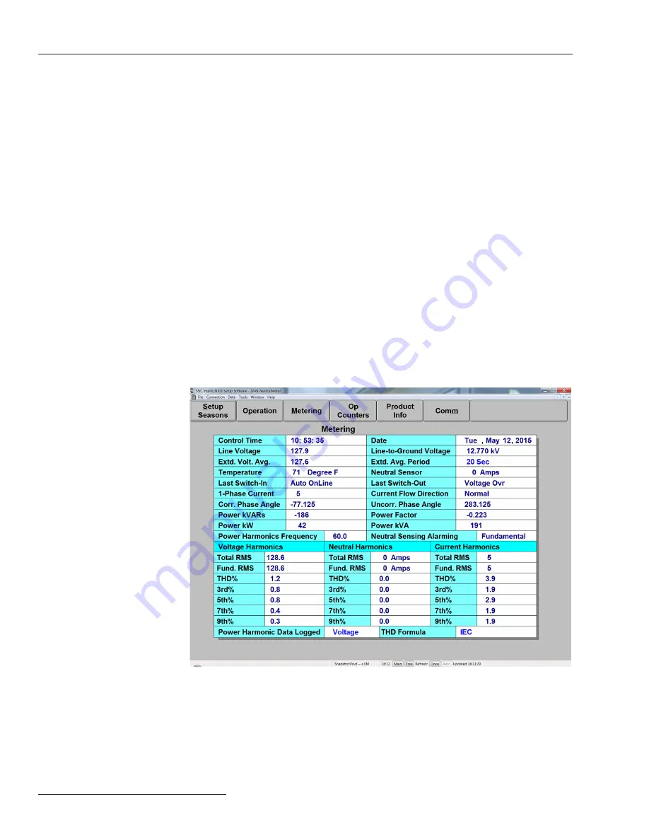
screen displays real-time data and the most recent calculated harmonics.
Except for the temperature and the harmonics, these fields are the true RMS amplitude
measurements for the three phases on the feeder. The capacitor control takes a measurement
every 0.3 seconds. It then averages four measurements and displays the 1.2-second averaged
value. See Figure 4. To display the
Metering
screen,
click on the
Metering
button from any
IntelliLink screen.
Metering Screen
Figure 4. The Metering screen for the var control.
The
Metering
screen includes the following fields:
Line Voltage
This is the present value of the voltage seen at the control (in volts), on the nominal
voltage base (for example, 120 Vac). The control software uses this value in calculating the
kvar values.


