16 S&C Instruction Sheet 761-545
Installation
S&C Instruction Sheet 761-545
16
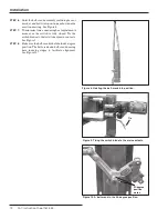
STEP 17.
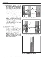
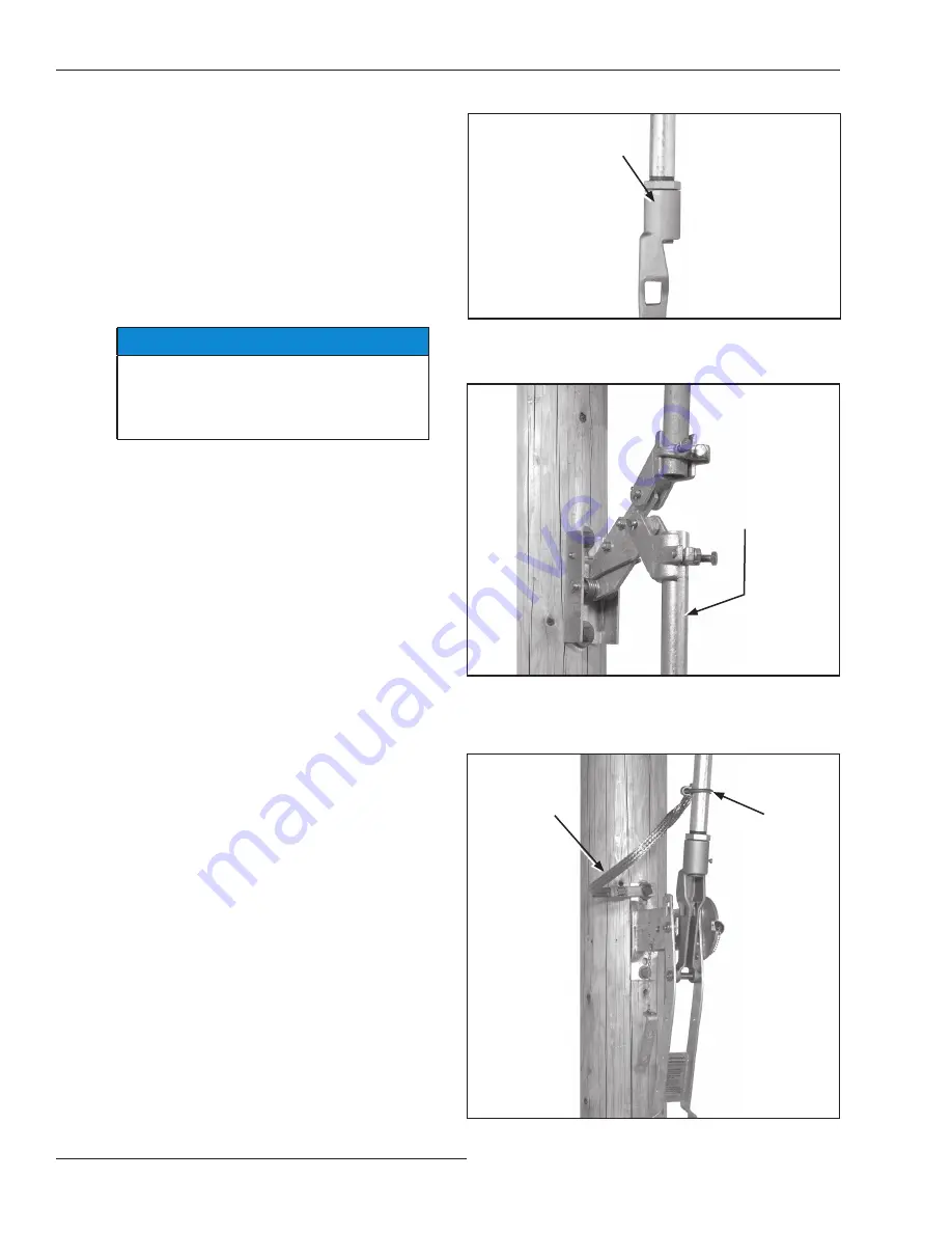
Install the lowest vertical operating-pipe
section by threading one end of the pipe into the
coupling on the operating handle. Approximately
¼-inch (6 mm) of thread should extend through
the coupling. Tighten the locknut. See Figure 19.
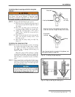
STEP 18.
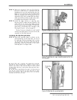
Insert the upper end of this pipe section in the
lowest rod-guide coupling (or, if only one
vertical pipe section is used, the bell-crank
coupling) and, while holding the operating
handle at a point approximately 20 degrees from
the
Closed
position, tighten the rod-guide (or
bell-crank) clamp bolt. See Figure 20.
NOTICE
Do not tighten the piercing set screw at the
top of the lowest section of vertical operating
pipe until satisfactory operating-handle
adjustment is attained .
STEP 19.
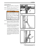
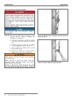
Fasten the free end of the grounding strap to the
lowest vertical operating-pipe section a few
inches above the operating-handle assembly
with the U-bolt connector provided for this
purpose. See Figure 21. Then, connect the lower
end of the strap to a suitable earth ground, using
the grounding connector provided at that end of
the strap .
●
●
If suffix “-S8” or “-S9” is specified, refer instead to S&C Instruction
Sheet 769-510, “S&C Switch Operators - Type AS-10 .” If suffix “-S16” is
specified, refer instead to S&C Instruction Sheet 1045M-510, “6801M
Automatic Switch Operators, Reciprocating and Rotating Switch Opera-
tion:
Installation
.”
Figure 19. Installing the lowest operating pipe section into
the operating handle assembly.
Locknut
Figure 20. Installing the lowest operating pipe section into
the rod guide.
Lowest section of the
vertical operating pipe
Figure 21. Attaching the grounding strap.
Grounding
strap
U-bolt
connector

