10 S&C Instruction Sheet 761-545
Installation
S&C Instruction Sheet 761-545
10
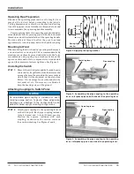
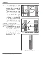
Spring-type
washer
Figure 2. Applying the spring washer.
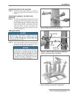
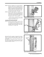
Figure 3. Assembling the pipe coupling to the operating
lever—interphase pipe on both sides of the operating lever.
Operating lever
Pipe coupling
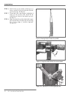
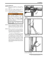
Figure 4. Assembling the pipe coupling to the operating
lever—interphase pipe on one side of the operating lever.
Operating lever
Pipe coupling
Operating Pipe Preparation
If desired, the operating pipes can be cut to length (if not
precut at the factory) before proceeding to the job site.
Cutting dimensions are shown on the erection drawing.
One of the pipe sections furnished is threaded at one end
to accommodate the operating handle assembly.
Users supplying their own operating pipe should deter-
mine which section of operating pipe is to be the lowest and
thread one end of it for installation of the operating handle.
Provide sufficient thread to allow the pipe to extend
approximately
¼
-inch (6-mm) below the handle coupling.
Mounting to Wood
When mounting the switch and its operating mechanism to
a wood structure or wood pole, S&C recommends suitably
sized square washers be placed under the nuts. S&C also
recommends using spring-type washers between the
square washers and nuts to compensate for wood shrink-
age and thus maintain fastener tightness. See Figure 2.
Uncrating the Switch
STEP 1.
Remove the switch poles and bell-crank base(s)
or bracket(s), if applicable, from their crates and
arrange them on the ground in the same order in
which they will be mounted on the structure.
Protect the bearings from contamination by
dirt, mud, oil, etc. If necessary, use blocks to
keep the bearings clear of the ground.
Attaching Couplings to Switch Poles
NOTICE
An adjustable pipe coupling is included for each
interphase pipe section . Typically, these adjustable
couplings are attached to the center switch pole
except for tiered-upright mounting configurations .
STEP 2.
Attach pipe couplings to the operating lever of
each switch pole. Each pipe coupling includes
¼
-inch (6-mm) and
⅜
-inch (10-mm) spacers.
Position the spacers, included with each
coupling, as shown in the section views on
the erection drawing. See Figures 3 and 4.


