


S&C Instruction Sheet 761-507
7
Shipping and Handling
Inspection
Examine the shipment for external evidence of damage as
soon after receipt as possible, preferably before removal
from the carrier’s conveyance. Check the bill of lading to
make sure the listed shipping skids, crates, and containers
are present.
If there is visible loss and/or damage:
1. Notify the delivering carrier immediately.
2. Ask for a carrier inspection.
3. Note condition of shipment on all copies of the delivery
receipt.
4. File a claim with the carrier.
If concealed damage is discovered:
1. Notify the delivering carrier within 15 days of receipt of
shipment.
2. Ask for a carrier inspection.
3. File a claim with the carrier.
Also notify S&C Electric Company in all instances of
loss and/or damage.
Packing
Study the erection drawing carefully and check the bill of
materials to be sure all parts are at hand. When a standard
mounting arrangement is specifi ed, the shipment includes:
• A three-pole interrupter switch complete with
interphase drive, factory assembled on a single base
(All switch adjustments, including that of the interphase
drive, are made at the factory to ensure proper operation
and simultaneity of opening and closing.)
• Three vertical operating-pipe sections (Switch may be
furnished “less operating pipe,” if specifi ed.)
• Operating-mechanism components, such as handle, rod
guides, and couplings—each tagged and keyed to the
bill of material for ready identifi cation
The components included with these modifications are
shown on the erection drawing bill of material under the
specified “-SX” suffix. They include:
-S1 One tubular fiberglass insulating section in vertical
operating shaft
-S2 One Cypoxy™ Insulator unit in vertical operating
shaft
-S6 Key interlock—single lock for a “locked-open”
application
-S6L Provision for key interlock—allows future addition
of single lock for “locked-open” application
-S7 Auxiliary contact switch with 4 N/O and 4 N/C
contacts (600 Vac, 20 A)
-S8 Provision for power operation of pole-mounted
switch by S&C Switch Operator—Type AS-10
-S9 Provision for power operation of steel-structure
or pedestal-mounted switches by S&C Switch
Operator—Type AS-10
-S16 Provision for power operation by S&C 6801M
Automatic Switch Operator
“-V1,” “-V2,” or “-V3” adds (one, two, or three respectively)
extra 6-foot-10-inch (208-cm) lengths of pipe and includes
the appropriate number of extra couplings and guides.
Reference drawing RD-10005, detailing the various
modifications, is included in addition to the erection
drawing.
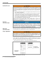
Power Operation:
If suffi x “-S8” or “-S9” is specifi ed,
S&C Instruction Sheets 769-510 and 769-511, “S&C Switch
Operators—Type AS-10,” are included with the switch
operator shipment. Instruction Sheets 769-510 and 769-
511 cover installation, operation, and adjustment of
the appropriate switch operator and should be used in
conjunction with this instruction sheet where applicable.
If suffi x “-S16” is specifi ed, associated S&C Instruction
Sheets for the 6801M Automatic Switch Operator are
included with the switch operator shipment. Not all
mounting arrangements are suitable for power operation;
consult the nearest S&C Sales Offi ce for details.
Handling
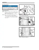
The crate the switch is packed in is designed to be moved
and lifted using a lift truck. Raised slots in the bottom of
the crate are provided for a lift truck’s forks.
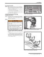
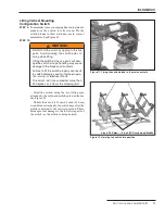
NOTICE
To minimize time-consuming final adjustments
after installation, make sure the switch poles are in
their fully
Closed position during installation of the
interphase and vertical operating pipe sections . S&C
recommends tying the switch blades to their jaw
contacts with wire or a cable tie .
WARNING
DO NOT lift the switch by rigging on the “live parts” or
subject these parts to undue stress from slings or fall
lines .
Lifting the switch by the live parts will damage the
switch . Rough handling may cause damage to the
blades and contacts .
Failure to lift the switch properly can result in
switch damage, causing improper operation,
arcing or electrical shock.