S&C Alduti-Rupter Additional Instructions For Installation And Operation Download Page 23

S&C Instruction Sheet 761-507   

23

Installation

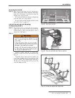
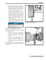
(g)  Move the blade assembly slowly toward the 

Closed

 position until the blade assembly is 

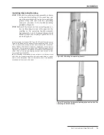
under the interrupter lever shaft. Verify the gap 
between the end of the interrupter lever shaft 
and the blade assembly is between and 

3∕16

-

inch 

(5 mm) and 

9�32

-inch (7 mm). See Figure 36.

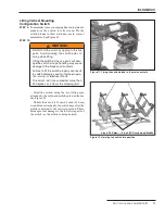
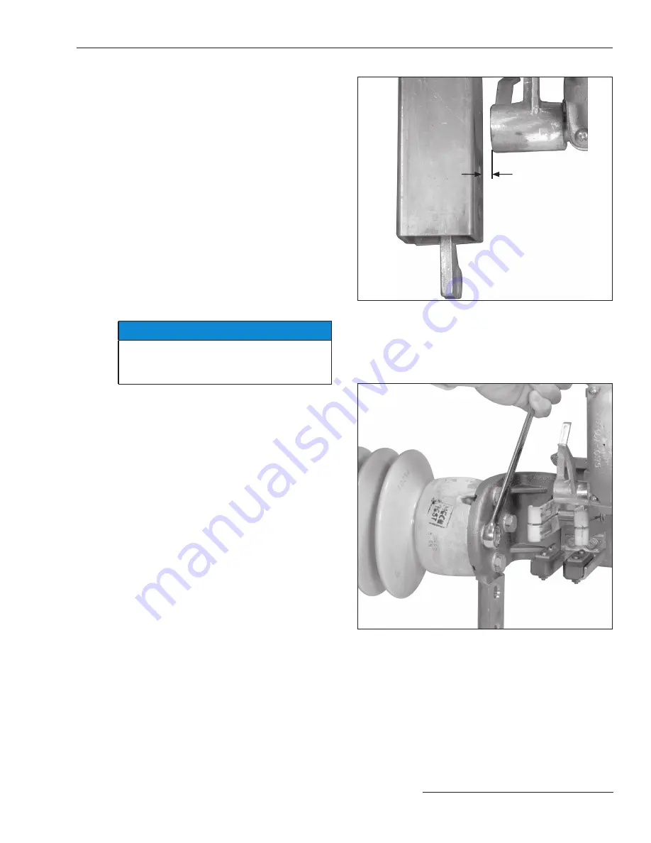
(h)  If the conditions described above are not met, 

adjust as follows. Loosen the four 

½

-inch–13 

×

1

¼

-inch hex-head galvanized steel cap screws 

that fasten the terminal base castings to the 
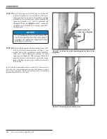
stationary insulators. See Figure 37. Shift the 
terminal base castings as required. Tighten the 
cap screws and recheck for conformance to the 
conditions outlined above. Readjust if required. 
Make certain the cap screws are tightened to 
fi nal tightness (55 ft.-lb.).

If any of the conditions described in this step 

cannot be achieved, contact the nearest S&C 
Sales Office because it is likely damage was 
sustained during shipment.

NOTICE

Stationary contacts are greaseless and 
self-lubricating . 

Do not apply lubricant to 

the stationary contacts .

Connecting High-Voltage Conductors 

When high-voltage conductors are to be connected 
using aluminum-alloy body connectors

 the following 

procedures should be used:

(a)  Thoroughly wire-brush the current-transfer 

surfaces of each connector and immediately 
apply a liberal coating of Penetrox® A (available 
from Burndy Corporation) to the brushed 
surfaces.

(b)  Wire-brush each terminal pad of the interrupter 

switch and apply a coating of Penetrox A. Then 
bolt the connectors to the terminal pads.

(c)  Prepare the conductors using established 

procedures and clamp them in their respec tive 
connectors.

(“Mass anode”-type connectors, such as the catalog number 6300 

series offered by S&C, that have been designated by the connector 
manufacturer as being suitable for direct attachment to copper  bearing 
alloy terminal pads .

Figure 36. Verifying the gap between the end of the interrupter 
lever shaft and the blade assembly.

Figure 37. Adjusting the position of the terminal base casting.

3∕16

-inch (5 mm) min, 

9/32

-inch (7 mm) max

Summary of Contents for Alduti-Rupter

Page 1: ...tions 4 Replacement Instructions and Labels 4 Location of Safety Labels 5 Safety Precautions 6 Shipping and Handling Inspection 7 Packing 7 Handling 7 Installation Mounting to Wood 8 Preparing the Pol...

Page 2: ...carefully read this instruction sheet and all materials included in the product s S C Instruction Handbook before installing or operating your S C Alduti Rupter Switch Familiarize yourself with the Sa...

Page 3: ...user s claim All other warranties whether express or implied or arising by operation of law course of dealing usage of trade or otherwise are excluded The only warranties are those stated in Price She...

Page 4: ...ecautions are not followed NOTICE NOTICE identifies important procedures or requirements that can result in prod uct or property damage if instructions are not followed Following Safety Instructions I...

Page 5: ...Hazard B WARNING Piercing Set Screws G 3176R1 C WARNING Handle Operation G 4400R5 D WARNING Electrocution Hazard Grounding Strap G 6596 G 6580 1 on tiered outboard mounting configuration switch G 658...

Page 6: ...ng in accordance with safe operating procedures and rules 4 SAFETY LABELS AND TAGS Do not remove or obscure any of the DANGER WARNING CAUTION or NOTICE labels and tags Remove tags ONLY if instructed t...

Page 7: ...iary contact switch with 4 N O and 4 N C contacts 600 Vac 20 A S8 Provision for power operation of pole mounted switch by S C Switch Operator Type AS 10 S9 Provision for power operation of steel struc...

Page 8: ...sired height for mounting the switch See Figure 3 Refer to the erection drawing STEP 2 Insert a inch diameter through bolt not fur nished into each hole as shown in Figure 4 Loosely attach a square wa...

Page 9: ...G DO NOT lift the switch by rigging to the live parts Avoid allowing the switch to swing while lifting Lifting the switch by the live parts will dam age the switch Rough handling may cause damage to t...

Page 10: ...ighten the bolts See Figure 9 Then remove the lifting slings STEP 8 Attach the pole bands to the switch base anchor brackets using the J bolts furnished Use a stiffening block under each nut See Figur...

Page 11: ...and contacts Failure to lift the switch properly can result in switch damage causing improper opera tion arcing or electrical shock The switch will role somewhat more than 90 degrees as it clears the...

Page 12: ...heads enter into the keyhole slot and open slotted hole in the switch base See Figure 13 STEP 12 Slowly lower the switch until it just bears on the through bolts Fully tighten the bolts See Figure 14...

Page 13: ...1 Makesurethecuttingtipofthepiercingsetscrewdoes not protrude through the body of the clamp 2 Insert the operating pipe section into the coupling and finger tighten the clamp bolt s 3 Adjust the opera...

Page 14: ...n the switch drive lever and the uppermost rod guide with the rod guide arm pointing upward at a 45 degree angle See Figure 19 A positioning stud is furnished that holds the rod guide at 45 degrees Fo...

Page 15: ...itch Operator as sig nified by the addition of the standard minor modification suffix S8 or S9 to the erection drawing number refer instead to S C Instruction Sheet 769 510 S C Switch Operators Type A...

Page 16: ...attained STEP 20 Fasten the free end of the grounding strap to the lowest vertical operating pipe section a few inches above the operating handle assembly with the U bolt connector provided for this...

Page 17: ...g adjust ments to the de energized switch When opening or closing an energized switch swing the operating handle vig orously through its full travel without hesitation Arcing and damage to the switch...

Page 18: ...nce in the operating linkage is essential to ensure positive switch closure Recheck to be sure all clamp bolts and pierc ing set screws have been torqued to final tight ness If a key interlock is not...

Page 19: ...s full travel CAUTION The switch should be opened and closed slowly only when checking for alignment and complete closure When opening or closing the switch in ser vice do not slow down or stop part w...

Page 20: ...edure lengthening the driven arm of the adjustable rod guide in one step increments and readjusting for full operating handle travel until full switch blade travel is attained f When satisfactory trav...

Page 21: ...he following conditions must be met a As the blade assembly moves in the closing direction each blade closing cam must make positive engagement with its respective inter rupter closing lever See Figur...

Page 22: ...equired to conform to these conditions e Also asthebladeassemblymovesinthe opening direction the two blade opening cams must simultaneously make positive engagement with their respective interrupter o...

Page 23: ...nt NOTICE Stationary contacts are greaseless and self lubricating Do not apply lubricant to the stationary contacts Connecting High Voltage Conductors When high voltage conductors are to be connected...

Page 24: ...reaking fault currents STEP 28 Remove the padlock from the locking bar on the operating handle assembly Withdraw the locking bar See Figure 38 a If the operating handle assembly is fur nished withakey...

Reviews: