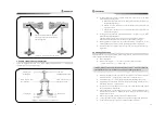
4”
Chapter 3. Initial setup after installation
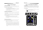
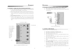
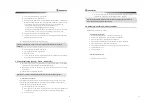
3.1 Controller for initial setup
button
Function
Operation
Working/S
etup
As the initial set switch is used for wiring operation. After completing all
installation, set switch to [set] position and control clutch lever, governor lever,
clutch sensitivity, governor sensitivity. After initial set, you should set [operation]
position. You should power on with [switch] position, it will operate as set
condition.
Upper
When the initial set is operated, lever and sensitivity controller are
as follows.
1. As numbers of FND indicator are one of 1,2,3,4,5,“ it is moved to pulled
fushcable while this switch is pressed.
2. As FND indicator number is ”, governor sensitivity is increased.
3. AS FND indicator number is 8, clutch sensitivity is increased.
low
When the initial set is operated, lever and sensitivity controller are as follows.
1. As numbers of FND indicator are one of 1,2,3,4,5,“ it is moved to pulled
fushcable while this switch is pressed.
2. As FND indicator number is ”, governor sensitivity is increased.
3. AS FND indicator number is 8, clutch sensitivity is increased
Input
Choice
As the initial set is operated, chosen switch is displayed on FND, whenever
putting button, 1~8 numbers are displayed in order.
Input
Input
This switch is to memory set value at each set item when the initial set is
operated. It is described that the moment of pressed control condition is stored
and operates as stored condition at normal operation.
A
y
~9
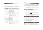
0 : Normal Operation
Set Operation(Set + Power ON)
Set Function(Set + PowerON)
FND
1 : Governor full speed set
2 : Governor slow speed set
3 : Clutch forward position set
4 : Neutral position set before
clutch
5 : Clutch astern position set
“ : Neutral position set after set
” : Governor sensitivity control
8 : Clutch sensitivity control
9 : Standard value set (On
delivering, set value)
1 : Governor automatic scope set
48
3.2 Operating setup (Setup + Power ON)
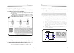
With ship's engine is off, check all electric wire, portable transmitters wire and fushlble
cable locking condition, set operation/set switch [set] position.
Main power supply switch (install outside of unit) ON, supplies power.
Governor Full position speed set
①
Check if operation/set switch is [set].
②
Press choice switch to set 1 on indicator
③
Set Governor controller of remote controller to set [FULL] position.
④
Press ▲ switch or ▼ switch to control Governor lever of Control lever(manual
controller) to be [FULL]speed position.
⑤
Press Input switch
⑥
In case of not the initial set, set operation/set switch to [operation]. Indicator would
be displayed 0 at normal operation.
Governor slow speed position set.
①
Check if operation/set switch is set [set].
②
Press choice switch to set 2 on indicator
③
Set Governor controller of remote controller to set [SLOW] position.
④
Press ▲ switch or ▼ switch to control Governor lever of Control lever(manual
controller) to be [SLOW]speed position.
⑤
Press Input switch
⑥
In case of not the initial set, set operation/set switch to [operation]. Indicator would
be displayed 0 at normal operation.
Clutch AHEAD position set.
①
Check if operation/set switch is set [set].
②
Press choice switch to set 3 on indicator
③
Set Governor controller of remote controller to set [AHEAD] position.
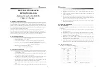
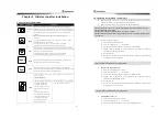
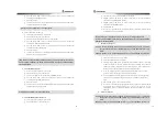
Caution As lover position is set to control lever with press switch, pay attention to not go
over top and bottom control scope.
Caution As all control is completed, notice Operation position
....
Caution After the initial set, follow normal action and be sure to check that engine-off after
all action test.
Caution Notice if fushble cable is too tightly pulled.
Caution Notice if fushble cable is too tightly pulled.


