


3
4.14 ADJUSTMENT OF SCREEN BRIGHTNESS............................................................................. 18
4.15 FUNCTIONS OF REMOTE CONTROLLER .............................................................................. 19
4.15.1 Remote Controller of RC-10A......................................................................................................19
Chapter 5. System Installation............................................................................... 20
5.1 BEFORE INSTALLATION............................................................................................................. 20
5.2 CONFIGURATION OF SYSTEM ................................................................................................. 20
5.3 INSTALLATION FOR AUTO PILOT............................................................................................ 20
5.3.1 Installation for display units............................................................................................................20
5.3.2 Installation for Compass sensor (Electronic Compass).......................................................21
5.3.3. Installation for Solenoid valve.......................................................................................................21
5.3.4 Installation for Transmitter...............................................................................................................22
Chapter 6. Hydraulic Piping ................................................................................... 23
6.1 Before Hydraulic piping............................................................................................................ 23
6.2 Piping diagram before installation for Solenoid valve....................................................... 23
6.3 Piping diagram after installation for Solenoid valve.......................................................... 24
6.4 Piping diagram at a cylinder type.......................................................................................... 25
Chapter 7. Electric Diagram ................................................................................... 27
7.1 Before hydraulic piping ............................................................................................................ 27
7.2 Interference to Radio equipment ........................................................................................... 27
7.3 Cautions in initial Power-On.................................................................................................... 27
Chapter 8. Initial Setup after installation ........................................................... 28
8.1 Initial setup ................................................................................................................................. 28
8.1.1 Power ON/OFF ......................................................................................................................................28
8.1.2 Rudder setup .........................................................................................................................................29
8.1.3 Remote setup.........................................................................................................................................31
8.1.4 Compass adjustment..........................................................................................................................32
8.1.5 System setup..........................................................................................................................................34
8.1.“ Option, Warning, Measurement....................................................................................................35
8.1.” Self test result........................................................................................................................................35
8.1.8 Adjustment for Solenoid valve ......................................................................................................3“
8.2 Self Test ....................................................................................................................................... 37
Chapter 9. Funtions of Alert and Trouble indicator ......................................... 38
9.1 Alert Function............................................................................................................................. 38
9.2 Remote Alert Funtion for adjustment ................................................................................... 38
9.3 Funtion for indicating troubles (Operate Error) .................................................................. 38
SM-975A ELECTRONIC LEVER................................................................................ 39
INSTRUCTION MANUAL ......................................................................................... 39
Chapter 1. Preview ................................................................................................... 39
1.1 Engine Control (SM-975A) ....................................................................................................... 39
1.2 Product Specificiation ............................................................................................................... 39
4
1.3 Cautions for operation ............................................................................................................. 39
1.4 Terms and abbreviation............................................................................................................ 40
1.4.1 Terms Explanation................................................................................................................................40
1.4.2 Abbreviation Explanation .................................................................................................................40
Chapter 2. System Installation............................................................................... 41
2.1 Installation of Control Cables.................................................................................................. 41
2.2 How to connect Control cables .............................................................................................. 42
2.3 Cable connection to manual lever.......................................................................................... 43
2.4 Wiring Connection..................................................................................................................... 44
2.5 Drawing for wiring connection (Connected to Auto Pilot) ............................................... 45
2.6 Drawing for wiring connection (Electronic lever separate type)...................................... 46
2.7 Cautions in initial power-on .................................................................................................... 46
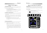
Chapter 3. Initial setup after installation............................................................ 47
3.1 Controller for initial setup ....................................................................................................... 47
3.2 Operating setup (Setup + Power ON) ................................................................................... 48
3.3 Functional setup (Setup + Power ON) .................................................................. 51
3.4 Default values for operation / functions .............................................................................. 52
Chapter 4. How to Operate.................................................................................... 53
4.1 Functions for Remote Controller ............................................................................................ 53
4.2 How to operate for Remote Contoller .................................................................................. 53
Chapter 5. Drawing for SM-975A ......................................................................... 55
5.1 Outline drawing for Electronic Lever ..................................................................................... 55
5.2 Outline drawing for Remote Controller ................................................................................ 55
5.3 System Configuration ............................................................................................................... 56
5.3.1 Configuration for Electronic Lever separate type (SM-9”5A) .......................................5“
5.3.2 Auto Steering / Electronic Lever (SAS-”0+SM-9”5A).........................................................5“
5.4 Connecting diagram for Electonic lever ................................................................................ 57
Chapter 6. PACKING LIST ..................................................................................... 58
6.1 SAS-70.......................................................................................................................................... 58
6.2 SAS-70 OPTION(In case of additional SM-975A) ................................................................ 60
Chapter 7. PRODUCTS DRAWINGS ...................................................................... 61
Chapter 8. Warranty................................................................................................. 65
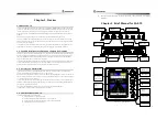
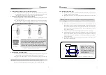
☞ Thank you for your purchasing of Auto Pilot manufactured by Samyung ENC.
☞ Pay attention to navigation owing to there is no alert function for collision on this unit.
☞ The specification might be changed for higher efficiency without any notice.
☞ Please look into this manual before operation.
☞ We propose you to turn off the power immediately if the units have wrong symptom.
☞ Keep this manual beside on the units all the time.