Samwontech TEMI2000 Series Operation Manual Download Page 16

SAMWONTECH 

4st Edition of TEMI2000_Series IM : Aug. 18. 2009                                                                                  Page    13 / 55 

3.2.4 The 3

rd

 FIX Operations screen 


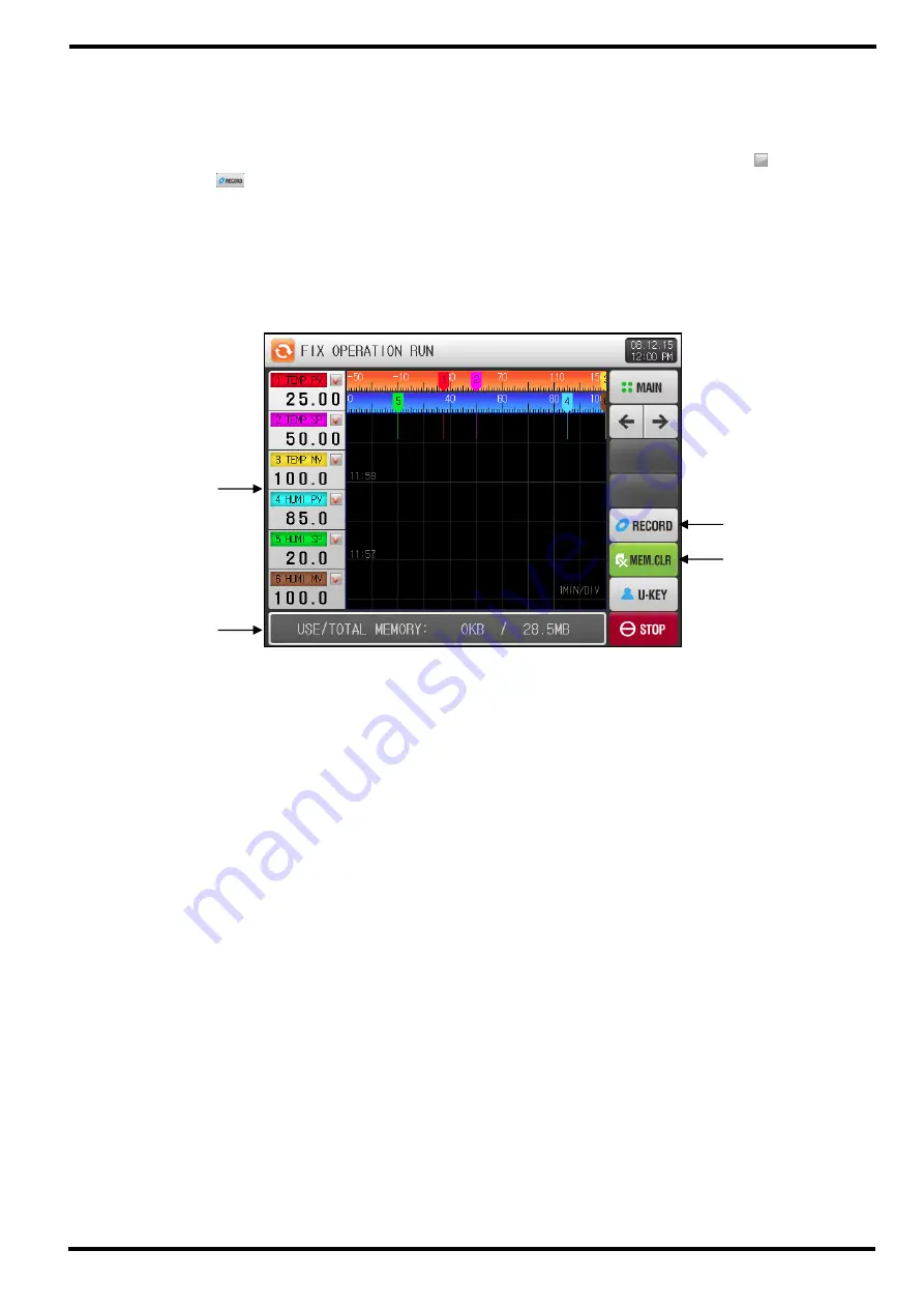
This screen is for viewing and recording data by trend graph.   


You can set items to display data by trend graph among 6 parameters – SP, PV, MV of temperature 

and humidity – shown at the left hand side of this screen by using each check box (


). 


Press  the 

(RECORD)  button  on  the  right  hand  side  to  store  the  recording  data  in  the  internal 

memory. 


All data saved in internal memory will be wiped out by POWER OFF. 


Store all important recorded data to SD card before POWER OFF 


Refer to [6.2 TREND GRAPH view & DATA processing]. 


While the data is recording into internal memory, that can not be downloaded to SD card. 


Displays the PV, SP, MV of temperature and humidity and its check box button. 


Displays available internal memory volume. 


About 25days can be saving on 1 second of sampling time. 


Button to start recording data selected by check box on the internal memory. 


Clear button to wipe out all data stored to internal memory. 


[Figure 3-7] The 3

rd

 FIX RUN Screen


Summary of Contents for TEMI2000 Series

Page 1: ...OPERATION MANUAL TEMPERATURE HUMIDITY PROGRAMMABLE CONTROLER TEMI2000 SERIES TEMI 2300 TEMI 2500 TEMI2700...

Page 2: ...8 3 2 FIX Operation 9 3 3 PROGRAM Operation 15 3 4 AUTO TUNING and TUNING POINT 20 4 FUNCTION FIX OPERATION setting 4 1 Operation mode Functions 21 4 2 FUZZY function 23 4 3 SP SLOPE function 24 5 PRO...

Page 3: ...2 2 7 SCREEN DISPLAY setting 7 1 Screen display setting 47 7 2 DI ERROR HISTORY 48 8 RESERVE OPERATION setting 50 9 USER SCREEN setting 9 1 USER SCREEN viewer 52 9 2 Creating BMP File for USER SCREEN...

Page 4: ...nd prior to operating C Symbolizes Supplementary Explanation The information with this symbol describes additional explanation for features D Symbolizes Reference This symbol indicates further informa...

Page 5: ...malfunction Limitation of Liability A SAMWONTECH does not guarantee or accept responsibility for this product other than the clauses stated in our warranty policy B SAMWONTECH assumes no liability to...

Page 6: ...reen will appear for loading time then Initial Logo screen will be displayed The screen will automatically progress to the STOP screen It takes around 18 seconds for loading Press the MAIN button at t...

Page 7: ...multiple options Button to set target Set Point of temperature and humidity and process time for each segment on 5 1 Program PATTERN Input Keypad will appear Button to select on of several modes or op...

Page 8: ...this Input Keypad If the setting value is out of the available range LIMIT ERROR message will appear with a BEEP sound and input will be rejected Numeric Keypad to input numerical values Alpha Numeri...

Page 9: ...input All Set Points can be set by using above mentioned numeric alpha numeric and Time Signal setting Keypad Numeric Input Keypad will appear with pressing button to input Set Point For the TIME SIG...

Page 10: ...0_Series IM Aug 18 2009 Page 7 55 Ex How to input Set Point The following describes how to change Set Point 49 40 to 12 5 Press the button to pop up Numeric Input Keypad Press the numbers by the order...

Page 11: ...ons Description GRAPH REC Section for display recoding data graph and its setting for SD card operation OPER SCREEN Operation status section to start display and set main operation parameters FUNCTION...

Page 12: ...TION FIX OPERATION setting when you press OPER SCREEN button on the MAIN MENU screen this FIX STOP screen will appear Target Set Point of temperature for FIX operation can be set through below Press t...

Page 13: ...4 Press the RUN button at the lower right corner to start operation after complete to input Set Point for temperature and humidity Table 3 1 Temperature Humidity SP Parameters Parameter Range Unit De...

Page 14: ...the next previous screen Button to carry out Auto Tuning process for temperature by target Set Point at To remove this tuning button from this screen refer to 10 PID GROUP on Installation Manual Butt...

Page 15: ...ctive RED Lamp indicates activating signal and relay ON state To select different DO signal display list on this screen refer to 13 2 Status Display Lamp on Installations Manual Displays the current r...

Page 16: ...internal memory All data saved in internal memory will be wiped out by POWER OFF Store all important recorded data to SD card before POWER OFF Refer to 6 2 TREND GRAPH view DATA processing While the d...

Page 17: ...OPERATION on 4 FUNCTION FIX OPERATION setting FIX operation will stop and TIME OPERATION END message appears shown as Figure3 8 However this message will not appear if the operation is stopped by forc...

Page 18: ...STOP screen will appear For program settings refer to 5 Program PATTERN Press the RUN button on Figure 3 9 PROGRAM STOP screen to start running operation and move to Figure 3 10 The 1 st PROGRAM Scre...

Page 19: ...staying current Set Point of temperature and humidity Button to step forward to next segment by skip current operating segment by force Button to carry out Auto Tuning process for temperature by curre...

Page 20: ...number Displays pattern repeat status Pattern Repeat status 000 000 The front number indicates total number for repeat process and the back number indicates completed repeat process number Displays s...

Page 21: ...to stop recording and recorded data will be stored in internal memory as a file New file will be created by every single turning ON OFF recording All data stored in internal memory will be wiped out...

Page 22: ...setting on processed pattern PROGRAM operation will stop and PATTERM OPERATION END message appears show as Figure3 13 However this message will not appear if the operation is stopped by force pressin...

Page 23: ...t Parameter Settings Operation method FIX operation Input sensor Temperature PT_1 Range 50 00 150 00 Auto Tuning Point 0 10 EUS 0 10 0 2 SP 50 0 OL 0 0 OH 100 0 Tuning Procedure Auto Tuning Precaution...

Page 24: ...fter recovery power recovery For FIX run state operation will re start from the beginning of TIME OPERATION For PROG run state operation will re start from the first segment of processed pattern HOT O...

Page 25: ...t OPERATION MODE PROG FIX ABS Pattern POWER STOP MODE STOP COLD HOT ABS STOP FUZZY SELECT OFF ON ABS Non function KEY LOCK OFF ON ABS OFF TEMP SP SLOPE T EUS 0 00 100 00 MIN T EUS MIN T EUS 0 00 MIN H...

Page 26: ...rol the overshoot that may occur when intense fluctuating load or frequent Set Point changing Before PV approaches to SP automatically calculated SUPER SP can restrain overshoot FUZZY OFF FUZZY ON PV...

Page 27: ...un operation NSP current SP will be changed from current PV to Target SP gradually by assigned ramping rate SP SLOPE Operation Operation mode FIX mode Ramping rate 20 0 min Amount of change to TSP SP...

Page 28: ...T menu is composed with 6 groups concerned program operation setting No Instructions Description PATTERN SET Pattern Segment setting group REPEAT SET Pattern Segment repeat operation setting group FIL...

Page 29: ...rt The program will begin operating from the assigned Start Set Point SSP of temperature humidity in the program and ramp to Target Set Point of segment 01 over time designated in segment 01 Start Set...

Page 30: ...I2000_Series IM Aug 18 2009 Page 27 55 Press the setup box and Input Keypad will appear Press the setup box and Option Keypad will appear Screen when TEMP SP setting of START CODE Setup box for Start...

Page 31: ...09 Page 28 55 Screen when HUMI SP setting of START CODE INSERT and DELETE buttons become active after activating specific segment by pressing Press the TEMP setup box and Input Keypad for TEMP SP will...

Page 32: ..._Series IM Aug 18 2009 Page 29 55 Press the HUMI setup box and Input Keypad for HUMI SP will appear Press the SEGMENT setup box and Input Keypad for TIME will appear Press the TIME SIGNAL setup box an...

Page 33: ...TIME SIGNAL by pressing TS1 TS4 button Table 5 1 PATTERN SET Parameters Parameter Range Unit Default PATTERN NUMBER 1 120 ABS 1 START CODE NOW PV TEMP SP HUMI SP ABS NOW PV TEMP SP of Segment n T EU...

Page 34: ...tion Setup box to input count number for partial repeat operation Displays of experiment name for current pattern The experiment name can be set at 5 6 PATTERN NAME This Displays is just READ ONLY and...

Page 35: ...ast target pattern to paste If setting 0 at END PATTERN only START PATTERN will be copied Displays total number of pattern set on 5 1 Program PATTERN This Displays is just READ ONLY and cannot be chan...

Page 36: ...essage will appear with no segment information at original pattern Table 5 3 FILE EDIT setting Parameters Parameter Range Units Default PATTERN NUMBER 1 120 ABS 0 START PATTERN 0 120 ABS 0 COPY TARGET...

Page 37: ...tting on 5 1 Program PATTERN 5 4 1 ON OFF Mode TIME SIGNAL operation TIME SIGNAL 0 is used for OFF not generating TS output duration of the program segment This is fixed READ ONLY and cannot be change...

Page 38: ...is to set the time to keep generating TIME SIGNAL ON at segment TS event output will be generating ON signal for OPER TIME When DEALY TIME OPER TIME Segment time TIME SIGNAL output will be generating...

Page 39: ...E SIGNAL 3 3 DELAY TIME 000 00 00 TIME SIGNAL 4 N SEG TIME DELAY TIME OPER TIME Does not affect the next segment 4 DELAY TIME 000 00 00 TIME SIGNAL 5 N 1 SEG TIME N SEG TIME N 1 SEG TIME SEGMENT OPER...

Page 40: ...ased and program operation will step to the next segment N 1 Setup box to set whether or not using WAIT Function Setup box to establish temperature WAIT ZONE to release WAIT Operation Setup box to est...

Page 41: ...e WAIT Operation by elapsed WAIT TIME WAIT TIME Set point WAIT ZONE WAIT ZONE PV Segment n Segment n 1 Segment n 2 WAIT Operation Actual Delay Time Release WAIT Operation Step to the next Segment n 1...

Page 42: ...he 1 st PROGRAM RUN Screen To input experiment name of each pattern Alpha numeric Input Keypad will pop up Button to move to the previous next 9 PATTERN SET page Press the button and the Alpha numeric...

Page 43: ...Figure 5 2 PATTERN SET screen by trend graph Even during processing operation it is adjustable to use Checkbox for Temperature Humidity and change pattern number and time unit for view display time B...

Page 44: ...aph Time interval for X axis can be adjusted as you want This is the Setup box for time interval Press the setup box and Option Keypad will popup on the screen This time interval can be adjusted even...

Page 45: ...eypad for pattern number to display by trend graph Table 6 1 PATTERN GRAPH VIEW setting Parameters Parameter Range Units Default PATTERN NUMBER 1 120 ABS 1 VIEW TIME 30 mins 1 hour 3 hours 6 hours 12...

Page 46: ...e humidity and its check box button whether or not to display Display recorded trend data by graph Remove recorded trend graph Button to move to the previous next screen Button to display the first la...

Page 47: ...2 nd FIX RUN screen for stored trend data file Files list stored in internal memory will popup with pressing the PV FILE button to be active Displays file list by 8 units at once You can select one sp...

Page 48: ...e PV graph is being saved About 37days can be saving on 1 second of sampling time Setup box for display range of temperature humidity Table 6 2 Trend Graph setting screen Parameters Parameter Set Rang...

Page 49: ...er Direction DOWNLOAD Transfer internal data of TEMI2500 to the SD card UPLOAD Transfer data in SD CARD to TEMI2500 Transfer Item PTN Program pattern profile information established on 5 1 Program PAT...

Page 50: ...lative Humpty AUTO The Humidity PV will be displayed if settings meet DRY LIMIT condition for Relative Humidity Otherwise will be displayed When humidity SP HSP 0 MANUAL Same to automatic except SP HS...

Page 51: ...cent 30 data will be displayed Displays DI ERROR history Name of settings are displayed within the 11 2 Error Name section of the Installation Manual This is READ ONLY and cannot be changed Button to...

Page 52: ...same DI 1 ERROR will be ignored for one minute even if DI 1 ERROR occurs once again during that time by the EXIT button while DI 1 ERROR However after one minute DI ERROR screen will be displayed by...

Page 53: ...the current year month date and time The time cannot be changed when the measured values are being recorded Setup box for the starting time of RESERVE Operation Button to activate RESEVER Operation b...

Page 54: ...nge Units Default YEAR 2000 2099 ABS MONTH 1 12 ABS DAY 1 31 ABS AM PM AM PM ABS HOUR 1 12 ABS CURRENT TIME MIN 0 59 ABS YEAR 2000 2099 ABS 2008 MONTH 1 12 ABS 1 DAY 1 31 ABS 1 AM PM AM PM ABS AM HOUR...

Page 55: ...ay if DI ERROR occurs while USER SCREEN viewing This button group will be popup on the screen by pressing touch screen during USER SCREEN viewing STOP button of USER SCREEN viewer and return to the Op...

Page 56: ...File Name USER SCREEN CS1 BMP CS2 BMP CS3 BMP CS14 BMP CS15 BMP CS16 BMP 16 in total INITIAL SCREEN INIT BMP DI ERROR PICTURE DI1 BMP DI2 BMP DI3 BMP DI14 BMP DI15 BMP DI16 BMP 16 in total File name...

Page 57: ...between the CONTROL UNIT and the DISPLAY PANEL occurs I O BOARD WAS DISCONNECTED message will appear on Operation screen shown as Figure 10 2 Communication Error with I O BOARD when communication erro...

Page 58: ...of instrument EUS The Engineering unit range based on the span of instrument EU EUS Range Range Central Point EU 0 100 RL RH RH RL 2 RL EU 100 100 RH RL RL RH RL EUS 0 100 0 RH RL RH RL 2 EUS 100 100...

Page 59: ...Wonmi gu Buchon si Gyeonggi do Korea 420 773 TEL 82 32 326 9120 FAX 82 32 326 9119 Website http www samwontech com e mail webmater samwontech com The contents of this document are subject to change wi...

Reviews: