background image

7.PIN Assignment   


DIV 

Socket Pin   

Description 

Input 

* Control Voltage/AC 85V

AC260V,50/60Hz   

(DC90V

DC370V) 

3 Phase application 

Phase L1 voltage 

Phase L2 voltage 

Phase L3 voltage 

1 phase application 

Phase L1 voltage 

Phase L2 voltage 

Output 

6-8-1 

Main trip/95-96-98,1c(SPDT) 


8. Indication feature 


Summary of Contents for DSP-DVR

Page 1: ...Digital 3 phase Voltage Relay DSP DVR DVR M DM II Meter...

Page 2: ...n 5 Preset Description 6 The order of Rotated Mode 7 PIN Assignment 8 Indication 9 Control Key Operation 10 Over voltage trip time characteristic 11 Trip Indication 12 Rotated Indication 13 Time Volta...

Page 3: ...eter 1 Abstraction Installation Model Protection Indication Panel Mounting Type DSP DVR Over Voltage Under Voltage Phase Loss Reverse Phase Line Average Voltage Frequency Panel Flush MountingType DSP...

Page 4: ...er under voltage reverse phase voltage unbalance v OFF is shown in case the line voltage is not sensed initially or voltage is dropped to zero 0 while the normal operation is doing Preset b in out mod...

Page 5: ...voltage voltage unbalance v OFF is shown in case the line voltage is not sensed initially or voltage is dropped to zero 0 rP is shown as main trip output 97 98 is still closed not trip after operatio...

Page 6: ...t relay 95 96 98 1c 1 SPDT 5A Resistive Application environment Temperature Operation 25O C 70O C Storage 40O C 80O C Humidity 30 85 relative non condensing Insulation Resistence IEC 60255 5 Case Circ...

Page 7: ...o make an initialization to factory default 000 Out a b to select initial state of main trip output initial state of main trip output is defined as followed condition a main trip output 95 98 1a is en...

Page 8: ...apsed continuously Auto reset is done in case line voltage is not loaded This mode is not available in case initial PL phase loss is happened OFF Otc dEF Inv to define voltage trip time charateristics...

Page 9: ...t dt is not interfaced with this mode OFF v Ub oFF setting value to preset voltage unbalance protection rate trip in case preset rate condition is kept on preset time or more rate Max V Min V Max V 10...
Page 10: ...v ot oFF setting value to preset delay time to show v oFF if voltage is not detected while working oFF disable for this mode preset time 1sec 10sec v ot is shown initially if voltage is not detected d...

Page 11: ...on for phase L2 voltage 0 vtPE to have a calibration for phase L3 voltage 0 to change Password Possible to enter new digit by using UP or DN key after positioning a cursor on the required digit Press...

Page 12: ...2 Control Voltage AC 85V AC260V 50 60Hz DC90V DC370V 7 5 3 Phase application Phase L1 voltage 4 Phase L2 voltage 3 Phase L3 voltage 5 1 phase application Phase L1 voltage 4 Phase L2 voltage Output 6 8...

Page 13: ...oing a prest job 3 SET Key CLR Key to select MODE Possible to select Mode by using SET or CLR key 4 UP key DN Key Adjust Possible to preset required value as selection a character or number by using U...

Page 14: ...to work normally or not tESt is appeared in case the operator press CLR key for 3 sec or more only in case control power is loaded without loading V1 V2 V3 then release pressed CLR key Trip output 95...

Page 15: ...se phase of incoming power line Phase loss trip caused by phase loss of incoming power line phase L2 Indication is shown based on RP condition if phase loss is occurred under RP state Volarge unbalanc...

Page 16: ...the voltage is not sensed or the voltage is dropped into 0V Zero Volt while normal operation is done If single phase is applied V OFF or actual voltage is shown dt trip delay time mode is preset OFF a...

Page 17: ...after dt is elapsed Main trip output 97 98 is trip after the sum of dt and operational time is elapsed in case initial line phase state is under reverse phase over under voltaege and voltage unbalance...

Page 18: ...case of line voltage by rotA ON OFF Bar graph indication DSP DVR M Type Operational state The ratio of a sensed voltage to preset ov value is shown e g preset value for ov 400V sensed voltage 320V th...

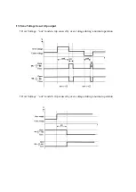
Page 19: ...13 Time Voltage based trip output Over Voltage out mode a trip caused by over voltage during a normal operation Over Voltage out mode b trip caused by over voltage during a normal operation...

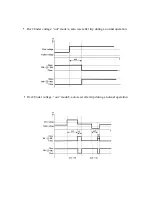
Page 20: ...Over Under voltage out mode a auto reset after trip during a normal operation Over Under voltage out mode b auto reset after trip during a normal operation...

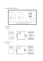
Page 21: ...14 Application Sequence Diagram 15 Dimension DSP DVR DSP DVR M Converter...

Page 22: ...60Hz Reference Code Description DSP DVR Panel Mounting Type 3Phase incoming voltage 8PIN Socket embedded Control power 85 260VAC 90 370 VDC Possible to fix line voltage in Line mode 100 500 VAC DSP DV...

Reviews: