background image

1-1 Safety Precautions  (Continued)

9. High voltage is maintained within specified

limits by close-tolerance, safety-related 
components and adjustments.  If the high 
voltage exceeds the specified limits, check
each of the special components. 

10. Design Alteration Warning:

Never alter or add to the mechanical or 
electrical design of this unit. Example: Do not
add auxiliary audio or video connectors. Such
alterations might create a safety hazard. Also,
any design changes or additions will void the
manufacturerÕs warranty.

11. Hot Chassis Warning:

Some TV receiver chassis are electrically 
connected directly to one conductor of the AC
power cord. If an isolation transformer is not
used, these units may be safely serviced only
if the AC power plug is inserted so that the
chassis is connected to the ground side of the
AC source.  

To confirm that the AC power plug is inserted 
correctly, do the following: Using an AC 
voltmeter, measure the voltage between the 
chassis and a known earth ground. If the 
reading is greater than 1.0V, remove the AC
power plug, reverse its polarity and reinsert.
Re-measure the voltage between the chassis
and ground. 

12. Some TV chassis are designed to operate with

85 volts AC between chassis and ground,
regardless of the AC plug polarity. These units
can be safely serviced only if an isolation
transformer inserted between the receiver and
the power source. 

13. Some TV chassis have a secondary ground

system in addition to the main chassis ground.
This secondary ground system is not 
isolated from the AC power line. The two
ground  systems are  electrically separated by
insulating material that must not be defeated
or altered.

14. Components, parts and wiring that appear to

have overheated or that are otherwise 
damaged should be replaced with parts that
meet the original specifications.  Always 
determine the cause of damage or overheat-
ing, and correct any potential hazards.

15. Observe the original lead dress, especially

near the following areas:  Antenna wiring,
sharp edges, and especially the AC and high
voltage power supplies.  Always inspect for
pinched, out-of-place, or frayed wiring.   Do
not change the spacing between components
and the printed circuit board.  Check the AC
power cord for damage.  Make sure that leads
and components do not touch thermally hot
parts. 

16. Picture Tube Implosion Warning:

The picture tube in this receiver employs
Òintegral implosionÓ protection.  To ensure
continued implosion protection, make sure
that the replacement picture tube is the same
as the original.

17. Do not remove, install or handle the picture

tube  without first putting on shatterproof
goggles equipped with side  shields.  Never
handle the picture tube by its neck.   Some 
Òin-lineÓ picture tubes are equipped with a 
permanently attached deflection yoke; do not
try to remove such Òpermanently attachedÓ
yokes from the picture tube.

18. Product  Safety Notice: 

Some electrical and mechanical parts have
special safety-related characteristics which
might not be obvious from visual inspection.
These safety features and the protection they
give might be lost if the replacement compo-
nent differs from the originalÑeven if the
replacement is rated for higher voltage,
wattage, etc.  

Components that are critical for safety are
indicated in the circuit diagram by shading,  
(      ) or (      ). 

Use replacement components that have the

same ratings, especially for flame resistance
and dielectric strength specifications. 
A replacement part that does not have the
same safety characteristics as the original
might create shock, fire or other hazards. 

Precautions

1-2

Samsung Electronics

!

Summary of Contents for WS28W6HA

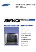
Page 1: ...BWT COLOR TELEVISION RECEIVER CONTENTS Precautions Reference Information Specifications Disassembly and Reassembly Alignment and Adjustments Troubleshooting Exploded View and Parts List Electric Parts List Wiring Diagram Schematic Diagrams 1 2 3 4 5 6 7 8 9 10 ...

Page 2: ...ELECTRONICS Samsung Electronics Co Ltd APR 1999 Printed in Korea 3SCT53A 6705 ...

Page 3: ... metal cabinets screwheads and control shafts The current measured should not exceed 0 5 milliamp Reverse the power plug prongs in the AC outlet and repeat the test Fig 1 1 AC Leakage Test 6 Antenna Cold Check With the unitÕs AC plug disconnected from the AC source connect an electrical jumper across the two AC prongs Connect one lead of the ohmmeter to an AC prong Connect the other lead to the co...

Page 4: ...ppear to have overheated or that are otherwise damaged should be replaced with parts that meet the original specifications Always determine the cause of damage or overheat ing and correct any potential hazards 15 Observe the original lead dress especially near the following areas Antenna wiring sharp edges and especially the AC and high voltage power supplies Always inspect for pinched out of plac...

Page 5: ...ssible conductive parts examples metal panels input terminals and earphone jacks 6 Insulation Checking Procedure Disconnect the power cord from the AC source and turn the power switch ON Connect an insulation resistance meter 500V to the blades of the AC plug The insulation resistance between each blade of the AC plug and accessible conductive parts see above should be greater than 1 megohm 7 Neve...

Page 6: ...ctrical charges that damage ESDs 5 Use only a grounded tip soldering iron when soldering or unsoldering ESDs 6 Use only an anti static solder removal device Many solder removal devices are not rated as Òanti staticÓ these can accumulate sufficient electrical charge to damage ESDs 7 Do not remove a replacement ESD from its protective package until you are ready to install it Most replacement ESDs a...

Page 7: ...rtz Hour Inches Per Second Kilowatt hour Kilogram Kilohertz Kilohm Kilometer Kilometer Per Hour Kilovolt Kilovolt ampere Kilowatt Liter Megahertz MV MW MΩ m µA µF µH µm µs µW mA mg mH mI mm ms mV nF Ω pF Ib rpm rps s V VA W Wh Megavolt Megawatt Megohm Meter Microampere Microfarad Microhenry Micrometer Microsecond Microwatt Milliampere Milligram Millihenry Milliliter Millimeter Millisecond Millivol...

Page 8: ...e Ground Green Y High High Frequency High Fidelity Inductance Capacitance Integrated Circuit Intermediate Frequency I O L L LED LF MOSFET MTS NAB NEC NTSC OSD PCB PLL PWM QIF R RC RF R Y SAP SAW SIF SMPS S N SW TP TTL TV UHF UL UV VCD VCO VCXO VHF VIF VR VTR VTVM TR Input output Left Low Light Emitting Diode Low Frequency Metal Oxide Semiconductor Field Effect Tr Multi channel Television Sound Nat...

Page 9: ... SDA9253 SDA9362 74F125 74F541 74F08 MSP3410D 74HC4052D Description Multi standard VIF PLL with QSS IF and AM demodulator RGB Video Processor 25W 25W Stereo Amplifier with Mute SY BY Audio Switching Low Drip Regulator 5V Regulator 12V Regulator 8V Regulator 9V AUTO PLUS OP AMP Component Interface Processor Video Processor Power On Reset Generator Display Processor VIP Memory Digital Deflection con...

Page 10: ...ification TDA7050 TL062C DPL3519A TL062C TDA6920X TL062C SDA30C264 ST24W16 TMS27C040 SAA1300 SDA5273P KM44C1000 TDA8351 TDA8145 STR S6709 TOP210ES TL431 LTV817B KA7805 TDA6111Q TDA2030 Description AUDIO AMP OP AMP Dolby Pro Logic Processor OP AMP 7 X 5 Video Matrix Switch OP AMP 8 bit Micro controller ROMILESS 16K EEPROM 512K 8 EPROM MEGATEXT IC DRAM DC coupled vertical deflection EW SMPS Stand by...

Page 11: ...QUENCY SIZE TYPE FRONT BACK 3 SCARTS Frequency Synthesizer PAL SECAM NTSC only AV mode NICAM A2 STEREO AM 75ohms Coaxial Cable 180W Main Voltage 230V Input Range 220 240V 50Hz 60Hz 30 76Cm 12 8 9 2 5R Invar 100 VHF 2 12 UHF 21 69 Cable S1 S41 Right 15W Left 15W Center 15W Surround 15W L R Right 15W Left 15W RCA Input S VHS Headphone Audio Output EXT1 full RGB Scart AV LINK EXT2 Scart Output Select...

Page 12: ...80 2401 000192 2301 000530 2401 000192 2301 000530 2301 000530 2401 000192 2401 000603 2401 000318 2401 000603 2401 002265 3711 000900 AA96 50279A 0801 000961 3812 000219 3812 000219 3812 000219 2001 001055 2001 001055 2001 001055 2001 001055 2001 001146 2001 000290 2001 000628 2001 000628 3812 000219 3812 000219 2001 000290 Specifications 3 2 Samsung Electronics 3 1 3D Sound Option Table Main Boa...

Page 13: ...276A 3722 001158 Loc No CN706 CN707 3 2 3D Sound Option Table AV Terminal Board Specifications Samsung Electronics 3 3 CW 30A80A 3D SOUND SPECIFICATION CODE NO CW 30A90SD DOLBY SOUND SPECIFICATION CODE NO RCA 5P 3722 001157 ...

Page 14: ...mbly Samsung Electronics 4 1 4 Disassembly and Reassembly 4 1 Back Cover Removal 1 7 2 3 5 4 6 4 2 Speaker Removal 1 After removing the 7 screws pull the cabinet backwards 1 Loosen the 4 screws and remove the Speaker Holders ...

Page 15: ...Disassembly and Reassembly 4 2 Samsung Electronics 4 3 CRT Removal 1 Spread a soft mat on the floor Place the TV set face down 2 Remove the 4 screws mounting the CRT to the front cabinet 3 Lift the CRT ...

Page 16: ...rmer 5 2 Automatic Degaussing A degaussing coil is mounted around the picture tube so that external degaussing after moving the TV should be unnecessary But the receiver must be properly degaussed upon installation The degaussing coil operates for about 1 second after the power is switched ON If the set is moved or turned in a different direction the power should be OFF for at least 10 minutes If ...

Page 17: ...anning lines in the center area of the screen 5 7 Purity Adjustment 1 Warm up the receiver for at least 20 minutes 2 Plug in the CRT deflection yoke Tighten the clamp screw 3 Plug the convergence yoke into the CRT and set it as shown in Fig 5 1 4 Input a black and white signal 5 Fully demagnetize the receiver by using an external degaussing coil 6 Turn the CONTRAST and BRIGHTNESS controls to maxim...

Page 18: ...ronics 5 3 4 Pole Magnet 6 Pole Magnet 2 Pole Magnet Clamper Screw 2 POLE PURITY YOKE CLAMP SCREW 6 POLE CONVERGENCE 4 POLE CONVERGENCE AD VE 31m m Vertical Green Belt Fig 5 1 Convergence Magnet Assembly Fig 5 2 Center Convergence Adjustment ...

Page 19: ...both tabs at the same time keeping the angle constant Superimpose the red and blue horizontal lines in the center of the screen 5 Adjust two tabs of 6 pole magnets Superimpose the red and blue lines with the green Adjusting the angle affects the vertical lines and rotating both magnets affects the horizontal lines 6 Repeat adjustments 2 4 if necessary 7 Since the 4 pole and 6 pole magnets interact...

Page 20: ... EW LowerCorner 2 11 P Hor EHT 90 12 P Ver EHT 90 13 P Bow 10 Option p1 00 EPG On 01 AV_LINK On 02 PAL Plus Off 03 12 8 9 Q On 04 16 9 Wide Off 05 Dolby Prologic On 06 3D Sound Off 07 S Audio Mute On 08 Blue Screen On 09 UHF Only Off 10 VGA Off 11 ATM ONE RUN On Service Mode p1 Video Adjustment Deflection Option Reset PICTURE OFF RED KEY DISPLAY P STD MUTE PICTURE OFF RED KEY 2 Use the channel and...

Page 21: ...5 6 Samsung Electronics MEMO ...

Page 22: ...4 RL802 D805 IC803 D802 D829 on the Power Board Check HD Signal on the Feature Box Module Check Replace IC201 TDA4780 ICA01 Auto Plus Tuner MICOM Module AUDIO Module A V Terminal Board TDA6920 Feature Box Module Check SDA1 SCL1 on the Micom Module No Replace Feature Box Module Check Replace Q405 D407 Q400 Q402 Q404 on the Power Board No Yes ...

Page 23: ...Check IC101 TDA9810 10 AGC 12 CVBS Check Replace IC101 Tuner Replace Feature Box Module No Check Feature Box Module M Y CVBS H SYNC HS2 Y SC100 Check IC201 TDA4780 14 SC 15 ABL 19 Cut off Replace TDA4780 No Check Replace IC501 IC502 IC503 on the CRT Board Yes Yes ...

Page 24: ...es No Check IC601 IC602 5 MUTE Check Replace Q602 Q603 Micom Module IC601 IC602 Check Replace IC101 Micom Module Audio Module No Check Audio Module MAIN L SUR CENTER S RESET QSS IN Check IC604 9 14 15 Check Replace IC604 MICOM Module No Replace IC601 IC602 Yes ...

Page 25: ...Exploded View Parts List Samsung Electronics 7 1 7 Exploded View Parts List 7 1 CS30A7HPTX BWT ...

Page 26: ...IOLET 1 1 6 AA64 40459A INDICATOR LED 307A ABS LG02431 1 1 7 AA95 90033G ASSY PCB A V SIDE CS767AHTR SCT53A PAL 1 1 8 6002 000514 SCREW TAPPING CF AV RH 2 M4 L15 ZPC BLK SWR 2 1 9 AA61 40105A SUPPORT CRT 2956 HIPS HB NTR 2 S N A 1 10 AA61 40010A BOSS WING HIPS HB NTR 1 S N A 2 AA03 10030U CRT COLOR A70QAZ761X002 DB 500mG 30 1 2 1 AA60 10050R SCREW ASSY CF CRT WC HH M5 L31 5 SWRCH18A ZPC 4 2 2 AA95...

Page 27: ...2401 001397 C AL 470uF 20 25V GP TP 10x16 5 C273 2301 000383 C FILM PEF 10nF 5 50V TP 6x7x3 2mm 5mm C864 2305 000665 C FILM MPEF 100nF 5 63V TP 7 5x4 0x5 0m C274 2305 000149 C FILM MPEF 100nF 5 100V TP 12x12 5x6 5 C866 2401 002273 C AL 220uF 20 25V HR TP 10x20mm 5m C275 2301 000356 C FILM PEF 47nF 5 50V TP 7 5x4 0x6 5 5m C870 2305 000665 C FILM MPEF 100nF 5 63V TP 7 5x4 0x5 0m C276 2301 000356 C F...

Page 28: ...000515 R CARBON 220OHM 5 1 8W AA TP 1 8X3 2MM IC803 1203 000203 IC POSI ADJUST REG 3050 TO 220 5P PLA H SINK R113 2001 001138 R CARBON S 390OHM 5 1 2W AA TP 2 4X6 4 IC804 1203 000243 IC POSI FIXED REG 7812A TO 220 3P PLA H SINK R116 2001 000938 R CARBON 68OHM 5 1 8W AA TP 1 8X3 2MM IC805 1203 000006 IC POSI FIXED REG 7808 TO 220 3P PLAS H SINK R121 2001 000522 R CARBON 22KOHM 5 1 8W AA TP 1 8X3 2M...

Page 29: ...30 C AL 100uF 20 100V GP TP 12 5x20 5 R622 2001 000429 R CARBON 1KOHM 5 1 8W AA TP 1 8X3 2MM C324 2401 000962 C AL 22uF 20 50V GP TP 5x11 5 R623 2001 000290 R CARBON 10KOHM 5 1 8W AA TP 1 8X3 2MM C401 2301 000247 C FILM PEF 33nF 5 50V TP 8 1x4 5x13mm 5 R624 2001 000273 R CARBON 100KOHM 5 1 8W AA TP 1 8X3 2M C402 2301 000213 C FILM PEF 220nF 5 250V TP 21 5x11 7 5 R626 2001 000522 R CARBON 22KOHM 5 ...

Page 30: ...6V WT TP 5x11 5 IC806 1203 000274 IC POSI FIXED REG 7805 TO 220 3P PLAS C842 2401 002211 C AL 1000uF 20 35V LZ TP 13x25mm 5 L301 AA27 40003G COIL HORIZ WIDTH 90 260UH SB 5SOS6 20 C843 2401 002289 C AL 470uF 20 35V WT TP 10x20 5 L302 3301 000287 CORE FERRITE BEAD AA 3 5x1x6mm 1500 2400 C844 2401 001840 C AL 100uF 20 16V GP TP 6 3x11 5 L303 3301 000287 CORE FERRITE BEAD AA 3 5x1x6mm 1500 2400 CLAMPA...

Page 31: ...OHM 5 1 2W AA TP 2 4X6 4M T444 AA26 30004STRANS FLYBACK FCZ 29A007 S 29 135V R411 2001 000066 R CARBON S 10KOHM 5 1 2W AA TP 2 4X6 4 T801 AA26 20006XTRANS SWITCHING 160 260V 130 30 24 8 1 R412 2004 001399 R METAL S 5 1Kohm 1 1 2W AA TP 2 4x6 4 T802 AA26 20004M TRANS SWITCHING 90 260V KS EE2118 7 92 R413 2001 001163 R CARBON S 560OHM 5 1 2W AA TP 2 4X6 4 R414 2001 001142 R CARBON S 3KOHM 5 1 2W AA ...

Page 32: ...F10 2001 000674 R CARBON 360OHM 5 1 8W AA TP 1 8X3 2MM DZ501 0403 000654 DIODE ZENER MTZ12B 12V 11 44 12 03V 500m RF11 2001 000362 R CARBON 150OHM 5 1 8W AA TP 1 8X3 2MM DZ502 0403 000654 DIODE ZENER MTZ12B 12V 11 44 12 03V 500m RF12 2001 000362 R CARBON 150OHM 5 1 8W AA TP 1 8X3 2MM DZ503 0403 000654 DIODE ZENER MTZ12B 12V 11 44 12 03V 500m RF13 2001 000429 R CARBON 1KOHM 5 1 8W AA TP 1 8X3 2MM D...

Page 33: ... 20 16V GP TP 5x11mm 5mm CD618 2203 000444 C CERAMIC CHIP 1nF 10 50V X7R TP 2012 C639 2401 002235 C AL 10uF 20 16V GP TP 5x11mm 5mm CD619 2401 002235 C AL 10uF 20 16V GP TP 5x11mm 5mm C640 2203 000938 C CERAMIC CHIP 470pF 5 50V NPO TP 2012 CD620 2401 002235 C AL 10uF 20 16V GP TP 5x11mm 5mm C641 2203 000142 C CERAMIC CHIP 1 5nF 10 50V X7R TP 2012 CD621 2203 000938 C CERAMIC CHIP 470pF 5 50V NPO TP...

Page 34: ...00931 R CHIP 470OHM 5 1 10W DA TP 2012 C718 2203 000192 C CERAMIC CHIP 100nF 80 20 50V Y5V TP R638 2007 000931 R CHIP 470OHM 5 1 10W DA TP 2012 C719 2203 000239 C CERAMIC CHIP 100pF 5 50V NPO TP 2012 R639 2007 000001 R CHIP 68KOHM 5 1 10W DA TP 2012 C720 2203 000938 C CERAMIC CHIP 470pF 5 50V NPO TP 2012 R641 2007 000001 R CHIP 68KOHM 5 1 10W DA TP 2012 C721 2203 000595 C CERAMIC CHIP 220pF 5 50V ...

Page 35: ...07 000738 R CHIP 30KOHM 5 1 10W DA TP 2012 D708 0401 000133 DIODE SWITCHING RLS4148 100V 200mA SOD 8 R718 2007 000931 R CHIP 470OHM 5 1 10W DA TP 2012 D709 0401 000133 DIODE SWITCHING RLS4148 100V 200mA SOD 8 R719 2007 000872 R CHIP 4 7KOHM 5 1 10W DA TP 2012 D710 0401 000133 DIODE SWITCHING RLS4148 100V 200mA SOD 8 R720 2007 000241 R CHIP 1 5KOHM 5 1 10W DA TP 2012 IC701 1001 001030 IC VIDEO SWIT...

Page 36: ... CHIP 100OHM 5 1 10W DA TP 2012 CP215 2401 000603 C AL 1uF 20 50V GP TP 5x11 5 R787 2007 000290 R CHIP 100OHM 5 1 10W DA TP 2012 CP216 2203 000221 C CERAMIC CHIP 100nF 20 50V Y5V TP 3216 R788 2007 000290 R CHIP 100OHM 5 1 10W DA TP 2012 CP217 2203 000578 C CERAMIC CHIP 220nF 20 50V Y5V TP 3216 R789 2007 000290 R CHIP 100OHM 5 1 10W DA TP 2012 CP218 2203 002085 C CERAMIC CHIP 56nF 10 50V X7R TP 201...

Page 37: ...RP128 2007 000941 R CHIP 47KOHM 5 1 10W DA TP 2012 C922 2203 000979 C CERAMIC CHIP 47nF 10 50V X7R TP 2012 RP130 2007 000872 R CHIP 4 7KOHM 5 1 10W DA TP 2012 C923 2203 000979 C CERAMIC CHIP 47nF 10 50V X7R TP 2012 RP131 2007 000586 R CHIP 22KOHM 5 1 10W DA TP 2012 C926 2203 000192 C CERAMIC CHIP 100nF 80 20 50V Y5V TP RP132 2007 000468 R CHIP 1KOHM 5 1 10W DA TP 2012 C927 2203 000979 C CERAMIC CH...

Page 38: ...330pF 10 50V Y5P TP R919 2007 000872 R CHIP 4 7KOHM 5 1 10W DA TP 2012 CN701A AA39 20067DLEAD CONNECTOR ASSY YBNH025 10 67096 0 R920 2007 000468 R CHIP 1KOHM 5 1 10W DA TP 2012 DZ701 0403 000654 DIODE ZENER MTZ12B 12V 11 44 12 03V 500m R921 2007 000872 R CHIP 4 7KOHM 5 1 10W DA TP 2012 DZ702 0403 000654 DIODE ZENER MTZ12B 12V 11 44 12 03V 500m R922 2007 000872 R CHIP 4 7KOHM 5 1 10W DA TP 2012 DZ7...

Page 39: ...MIC CHIP 100nF 80 20 50V Y5V TP C262 2401 002594 C AL 220uF 20 16V GP TP 8x11 5 5 AA95 90037EASSY FEATURE BOX CX724AHD SCT53A 100Hz C263 2203 000192 C CERAMIC CHIP 100nF 80 20 50V Y5V TP C264 2203 000192 C CERAMIC CHIP 100nF 80 20 50V Y5V TP C200G2203 000578 C CERAMIC CHIP 220nF 20 50V Y5V TP 3216 C265 2203 000192 C CERAMIC CHIP 100nF 80 20 50V Y5V TP C201 2203 000192 C CERAMIC CHIP 100nF 80 20 50...

Page 40: ...RAMIC CHIP 220pF 5 50V NPO TP 2012 R220 2007 000401 R CHIP 150OHM 5 1 10W DA TP 2012 CF08 2203 000661 C CERAMIC CHIP 270pF 5 50V NPO TP 2012 R221 2007 000267 R CHIP 1 8KOHM 5 1 10W DA TP 2012 CF09 2203 000938 C CERAMIC CHIP 470pF 5 50V NPO TP 2012 R222 2007 000947 R CHIP 47OHM 5 1 10W DA TP 2012 CN203A 3711 002709 CONNECTOR HEADER NOWALL 12P 1R 2 5MM ANG R223 2007 000947 R CHIP 47OHM 5 1 10W DA TP...

Page 41: ...IP 33OHM 5 1 10W DA TP 2012 FRONTAA64 31108LCABINET FRONT 767A DG703 CIS NEW HIPS R436 2007 000781 R CHIP 33OHM 5 1 10W DA TP 2012 BACK AA64 31109ECABINET BACK 767A HIPS V2 BLK R437 2007 000781 R CHIP 33OHM 5 1 10W DA TP 2012 IN AV AA64 60423LINLAY AV CS767A SCT53A L G PS T0 3 BLK R438 2007 000781 R CHIP 33OHM 5 1 10W DA TP 2012 BADGEAA64 70117BBADGE BRAND AL SS SILVER L65 R2000 R439 2007 000781 R...

Page 42: ...A TO AV CONTROL GND C IN GND Y IN GND R IN L IN GND HP R HP L CN08A TO AV CONTROL KEY GND STD 5V CN07A TO POWER SW GND STD 5V R LED G LED IR CNFAC SCL2 SDA2 NC NC GND FACT SCL1 SDA1 ST5V POWER BOARD MAIN BOARD POWER SW AC CORD MASTER REMOCON MOD AV CONTROL KEY VIDEO S VHS INPUT HEADPHONE OUTPUT GT808 GT809 TO PFC GT801 GT802 GT803 TO POWER SW GND 34V GND GND NC NC NC CN17 3P TO CENTER SPEAKER CN15...

Page 43: ...10 Schematic Diagrams Samsung Electronics Schematic Diagrams 12 1 10 1 MAIN 1 ...

Page 44: ...10 2 MAIN 2 Schematic Diagrams 12 2 Samsung Electronics ...

Page 45: ...10 3 POWER DEFLECTION Samsung Electronics Schematic Diagrams 12 3 ...

Page 46: ...10 4 TTX m COM Schematic Diagrams 12 4 Samsung Electronics ...

Page 47: ...Samsung Electronics 10 5 AUDIO MODULE Schematic Diagrams 12 5 ...

Page 48: ...10 6 AV TERMINAL Schematic Diagrams 12 6 Samsung Electronics ...

Page 49: ...Samsung Electronics 10 7 CRT DRIVE SIDE A V POWER S W SNAP IN Schematic Diagrams 12 7 ...

Page 50: ...10 8 PIP Schematic Diagrams 12 8 Samsung Electronics ...

Page 51: ...10 9 FEATURE BOX Samsung Electronics Schematic Diagrams 12 9 ...

Reviews: