background image

14_


connection and installation

connection and installation

uSe of communication


Coaxial communication system

connection and inStallation

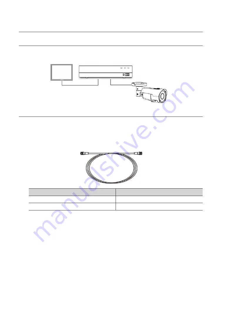
video cable

Connect the video output jack of the camera to the monitor with BNC coaxial cable, as shown below: Please use an 

auxiliary video amplifier if the distance between the camera and monitor exceeds the recommended maximum 

value.

Distance

Recommended cable specification

500m

5C2V

300m

3C2V


M


`

It is recommended to use the pure copper coaxial cable instead of the copper-clad iron cable, otherwise, it will result in 

problems of the communication via the coaxial cable.


`

To guarantee the image quality, only use single-channel video output connector when connecting the camera to other video 

equipment.

DVR


Summary of Contents for Wisenet SDC-9443BV

Page 1: ...SDC 9443BV 1080p HD Analog Bullet Camera User Manual...

Page 2: ...ced distributed or changed partially or wholly without formal authorization Disclaimer Hanwha Techwin makes the best to verify the integrity and correctness of the contents in this document but no for...

Page 3: ...grounding prong The wide blade or the third prong are provided for your safety If the provided plug does not fit into your outlet consult an electrician for replacement of the obsolete outlet 10 Prot...

Page 4: ...ric shock or damage to the product 3 Do not connect multiple cameras to a single adapter Exceeding the capacity may cause abnormal heat generation or fire 4 Securely plug the power cord into the power...

Page 5: ...re or damage to the product 5 Keep out of direct sunlight and heat radiation sources It may cause fire 6 Install it in a place with good ventilation 7 Avoid aiming the camera directly towards extremel...

Page 6: ...tallation 9 9 Before Installation 11 Adjustment of the Monitoring Direction of the Camera Connection and Installation 13 13 Connection of DVR and monitor 13 Power connection 14 Use of Communication 14...

Page 7: ...ea and reducing exposure for the bright area resulting in a clear detailed and accurate image Other Features HLC BLC V Flip Mirror Rotate Sharpness and Privacy Zone Communication Support Coax UTC Comm...

Page 8: ...rt to the Video IN port of an AHD DVR e Power input terminal Connect the power as specified DC 12V f Lens g Screws of Lens Distance Adjustment Cover h Lens Distance Adjustment Cover i Illumination Sen...

Page 9: ...ectric line cover to be damaged Otherwise it may cause a breakdown or fire When installing your camera don t allow any person to approach the installation site If you have any important issue to be de...

Page 10: ...osition to make sure it points to the area you would like to monitor J J Please mind the installation position Please do not touch the camera lens to avoid any dirt and dust FOCUS LEVER FAR NEAR ZOOM...

Page 11: ...fixed on the ceiling J J Images of some angles may be occluded by the camera housing Adjustment method 1 After installing the camera adjust by 0 90 degrees vertically and 0 360 degrees horizontally a...

Page 12: ...tect from water 1 Connect power supply and BNC power source 2 Cover black sheath of the cable Zone A and ensure half of butyl rubber can cover thecable joint J J Poor water protection at the cable she...

Page 13: ...C 68 F Copper wire size AWG 24 0 22mm 22 0 33mm 20 0 52mm 18 0 83mm Resistance m 0 078 0 050 0 030 0 018 Voltage drops V m 0 028 0 018 0 011 0 006 As shown in the table the voltage will be reduced whe...

Page 14: ...ideo amplifier if the distance between the camera and monitor exceeds the recommended maximum value Distance Recommended cable specification 500m 5C2V 300m 3C2V M M It is recommended to use the pure c...

Page 15: ...e sub menu and do the settings The item with icon is not available due to function setting Main menu EXPOSURE MAIN MENU EXPOSURE SHUTTER NTSC AUTO FLK 1 50 000sec 1 30sec X2 X30 PAL AUTO FLK 1 50 000s...

Page 16: ...een Adjust the level as needed to adjust the image brightness of D WDR LEVEL Level 0 to 8 optional And the higher the level the brighter the dark object RETURN RET SAVE END DEFOG POS SIZE POSITION and...

Page 17: ...ion of setting area AREA1 TO AREA4 DISPLAY POSITION and SIZE of setting area BLACK MASK Switch of setting area LEVEL Strong light inhibition level 0 100 The strong light inhibition is more obvious wit...

Page 18: ...all be adjusted MANUAL Choose MANUAL to adjust the white balance manually BLUE 0 100 optional The larger the value the bluer the image RED 0 100 optional The larger the value the redder the image RETU...

Page 19: ...haracter you choose through the menu option key Left Right Up and Down keys and click to confirm Repeat the step to input more characters 15 characters can be entered at most Move to the left or right...

Page 20: ...as to achieve effective monitoring SELECT 4 Areas optional DISPLAY Set the position and size of the Motion area SENSITIVITY Level 0 100 adjustable The higher the level the more sensitive it is COLOR T...

Page 21: ...Alarm time setting 0 15s RETURN RET SAVE END DEFAULT Restore defaults RETURN RET SAVE END M M The same settings of motion sensitivity apply to area both area 1 area 2 and area 3 area 4 The same settin...

Page 22: ...guage you need to set ENG GER FRA ITA SPA RUS POR TUR RETURN RET SAVE END M M When area of Motion and Privacy overlaps if set color under Display and set 1 as Transparency under Privacy setup overlapp...

Page 23: ...pid change of lighting The motion of fixed object on the same position occurs continuously Just like the object is close to the camera or keeps away from the camera the position on the image may move...

Page 24: ...s 928 576 Horizontal Resolution Centre 900 TV lines Corner 600 TV lines Lens Type Focal Length Zoom Ratio 2 8 12mm 4 3x varifocal Max Aperture Ratio F1 4 Angular Field of View D 115 2 40 H 98 6 36 8 V...

Page 25: ...50 000sec 1 25sec X2 X30 Reverse Off Mirror V Flip Rotate Protocol ACP Video Transmission Distance 300m 3C 2V 500m 5C 2V Environmental Operating Temperature Humidity 30 C 50 C 22 F 122 F Less than 90...

Page 26: ...26_ appendix appendix Product Overview unit mm inch 8 39 3 31 3 19 9 13 0 1 7 3 31 2 60 5 24 3 86...

Page 27: ...le condition for the monitor or DVR y y If the camera is pointed to the strong light please change the position of camera The image on the screen is dark y y Adjust the contrast ratio of monitor or DV...

Page 28: ...ble harm to the environment or human health from uncontrolled waste disposal please separate these items from other types of waste and recycle them responsibly to promote the sustainable reuse of mate...

Page 29: ...5489 www hanwha security com Hanwha Techwin America 500 Frank W Burr Blvd Suite 43 Teaneck NJ 07666 Toll Free 1 877 213 1222 Direct 1 201 325 6920 Fax 1 201 373 0124 Hanwha Techwin Europe Heriot Hous...

Reviews: