


3. Disassembly and Reassembly
3-2. Standard disassembly drawings
► This is a standard disassembly diagram and may differ from the actual product.Use this material as a reference
when disassembling and reassembling the product.
Part
Figure
Description
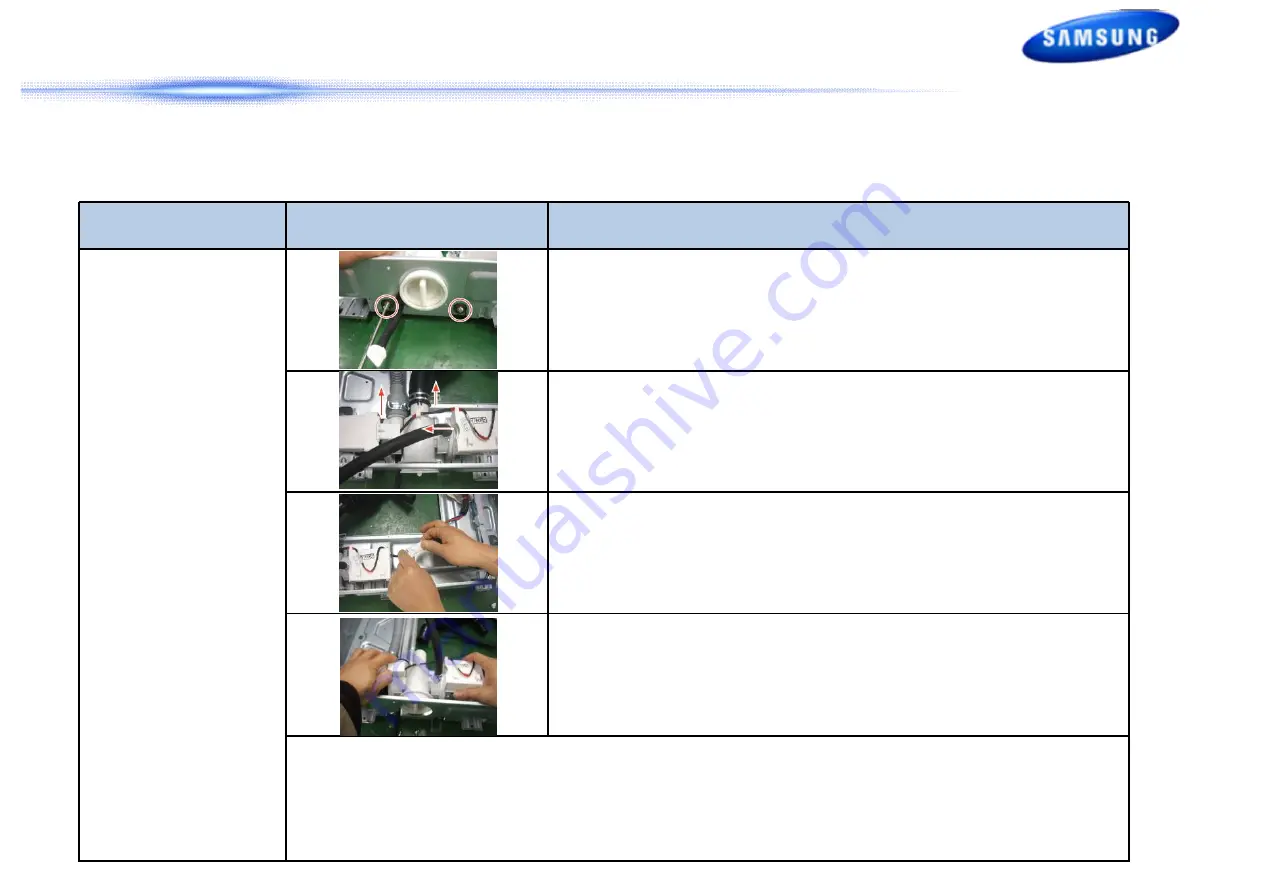
DRAIN PUMP
(Continued)
4. Remove the 2 screws holding the Drain Pump.
5. Drain the remaining water through the drainage hose.
6. Disconnect the wire connector.
7. Push it back and lift it up.
◆
Check Points for Troubleshooting
1. Separate the Drain Filter and check if any alien substances are inside the pump (e.g. coins, buttons, etc.)
→ Remove these if found.
2. Check if the wire connector for the Drain Pump ASSY has come loose. Reconnect if necessary.
3. When water leaks, check the assembly status of the Clamp Hose, and Cap Drain → Take the relevant countermeasure if
necessary.Turn the filter cap counterclockwise, clean and remove any material that has collected.
28/54
Summary of Contents for WF42H5 Series
Page 6: ...1 Product Introduction New Feature SpeedSpray 5 54 ...
Page 36: ...5 Test Mode Error Check Test Mode Diagram 35 54 ...
Page 44: ...5 Test Mode Error Check Fast Time Down Test Mode 43 54 ...
Page 45: ...5 Test Mode Error Check Fast Time Down Test Mode 44 54 ...
Page 50: ...6 PCB Diagram 49 54 ...
Page 51: ...6 PCB Diagram 50 54 ...
Page 52: ...6 PCB Diagram 51 54 ...
Page 53: ...6 PCB Diagram WF45H6 WF42H5 CONNECTOR AND RELAY PORT PART DETAILED MANUAL MAIN PCB 52 54 ...
Page 54: ...7 Reference Information 53 54 ...
Page 55: ...Thank you 54 54 ...


