4-2
Disassembly and Reassembly
Samsung Electronics
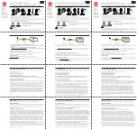
Fig. 4-4 Ass’y LCD & CVF/Jack Removal
4-1-3 Ass’y Left Removal
´
REMOVE 2 SCREWS
(M1.7 X 4 BLK)
ˇ
REMOVE 2 SCREWS
(M1.7 X 4 BLK)
¨
REMOVE 1 SCREW
(M1.7 X 4 WHT)
Œ
REMOVE 1 SCREW
(M1.7 X 4 BLK)
Caution :
Please indicate that the connectors
must be detached before separating
the Left Assembly
Fig. 4-3 Ass’y Left Removal
4-1-4 Ass’y LCD & CVF/Jack Removal
Caution :
Please indicate that the connectors
must be detached before separating
the EASY.Q Assembly
Caution :
Please indicate that the connectors
must be detached before separating
the LCD Assembly
Caution :
Please indicate that the connectors
must be detached before separating
the CVF Assembly
Œ
REMOVE 4 SCREWS
(M1.7 X 4 BLK)
∏
REMOVE 2 SCREWS
(M1.7 X 4 BLK)
¨
REMOVE 1 SCREW
(M1.7 X 4 BLK)
ˇ
REMOVE 2 SCREWS
(M1.7 X 4 BLK)
Ø
REMOVE 2 SCREWS
(M1.7 X 3 BLK)
´
REMOVE 2 SCREWS
(M1.7 X 5 BLK)
ˆ
REMOVE 4 SCREWS
(M1.7 X 5 BLK)
Summary of Contents for VP-D451
Page 10: ...Product Specification 2 4 Samsung Electronics MEMO ...
Page 30: ...3 20 Alignment and Adjustments Samsung Electronics MEMO ...
Page 46: ...4 16 Disassembly and Reassembly Samsung Electronics MEMO ...
Page 66: ...Exploded View and Parts List 5 20 Samsung Electronics MEMO ...
Page 84: ...Wiring Diagram 8 2 Samsung Electronics MEMO ...
Page 86: ...PCB Diagrams 9 2 Samsung Electronics 9 1 Main PCB COMPONENT SIDE ...
Page 87: ...PCB Diagrams Samsung Electronics 9 3 L708 Œ ˇ ˆ L704 L706 L717 L719 ...
Page 88: ...PCB Diagrams 9 4 Samsung Electronics CONDUCTOR SIDE Fuse 1 25A 32V ...
Page 94: ...PCB Diagrams 9 10 Samsung Electronics MEMO ...
Page 128: ...Troubleshooting 12 8 Samsung Electronics MEMO ...
Page 140: ...Circuit Operating Description 13 12 Samsung Electronics MEMO ...
Page 184: ...Reference Information 14 44 Samsung Electronics MEMO ...