3-4
Alignment and Adjustments
Samsung Electronics
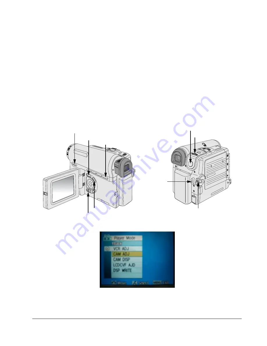
5) How to set up the camera adjustment mode
[STEP 1]
Œ
Connect the Power source.
´
Set the Power Switch to “CAM” position and Mode Switch to “TAPE” position.
[STEP 2]
Œ
Press and hold the "STOP" and "PB ZOOM" buttons on the video camera at the same time for more than
5 seconds.
´
When monitor OSD appears as shown Fig. 3-5, the adjustment mode has been activated successfully.
ˇ
Move the “MENU Selector” to highlight CAM ADJ and push the “MENU Selector”.
¨
Monitor OSD shows Fig. 3-6.
Then Camera adjustment mode has been activated successfully.
[STEP 3]
In order to complete the adjustment the power must be reset.
This can be done by disconnecting and reconnecting the power source.
Fig. 3-5
Fig. 3-4
MENU Button
EASY Q Button
Start/Stop Button
MENU Selector
DISPLAY Button
Mode switch
PB ZOOM
Power switch
STOP Button
DV
USB
AV
MIC
Summary of Contents for VP-D353
Page 8: ...Product Specification 2 4 Samsung Electronics MEMO ...
Page 24: ...3 16 Alignment and Adjustments Samsung Electronics MEMO ...
Page 58: ...Exploded View and Parts List 5 18 Samsung Electronics MEMO ...
Page 80: ...Wiring Diagram 8 2 Samsung Electronics MEMO ...
Page 82: ...PCB Diagrams 9 2 Samsung Electronics 9 1 Main PCB COMPONENT SIDE ...
Page 83: ...PCB Diagrams Samsung Electronics 9 3 CLK_41 85MHz Œ ˇ ˆ Ø Q708 Q707 Q706 Q704 Q703 Q702 Q701 ...
Page 84: ...PCB Diagrams 9 4 Samsung Electronics CONDUCTOR SIDE ...
Page 90: ...PCB Diagrams 9 10 Samsung Electronics 9 10 CVF PCB COMPONENT SIDE CONDUCTOR SIDE ...
Page 122: ...Operating Instructions 11 10 Samsung Electronics MEMO ...
Page 130: ...Troubleshooting 12 8 Samsung Electronics MEMO ...
Page 154: ...Reference Information 14 12 Samsung Electronics Loading state Unloading state Fig 14 11 ...
Page 164: ...Reference Information 14 22 Samsung Electronics Fig 14 16 LOADING POSTION UNLOADING POSTION ...


