


15
Ⅱ. INSTALLATION & FAQ
●
If you have installed the camera driver, The [Found New Hardware Wizard] may not open.
●
On a Windows 98 or 98 SE system, the Found New Hardware Wizard dialog box opens and a window asking
you to select a driver file may appear. In this case, specify "USB Driver" in the CD supplied.
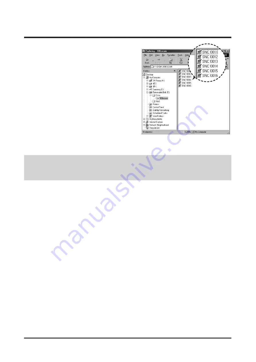
5. After restarting the computer, connect the PC to the
camera with the USB cable.
6. Turn on the camera power.
The [Found New Hardware Wizard] will open and the
computer will recognise the camera.
※
If your OS is Windows XP, an image viewer program
will open.
If the download window of Digmax Master opens after
starting Digimax Master, the camera driver was set up
successfully.
Summary of Contents for VLUU NV10
Page 1: ......
Page 14: ...14 Ⅱ INSTALLATION FAQ 4 Install the Digimax Master in order ...
Page 48: ...48 Ⅳ ADJUSTMENT 6 The Upgrade will start with displaying the following message ...
Page 55: ...55 Ⅳ ADJUSTMENT Open the file with the Memo pad ...
Page 75: ...75 Ⅳ ADJUSTMENT Open the file with the Memo pad ...
Page 82: ...82 Ⅳ ADJUSTMENT Open the file with the Memo pad ...
Page 105: ...Ⅴ PATTERN DIAGRAM 105 1 PARTS ARRANGEMENT FOR EACH PCB ASS Y 1 MAIN_TOP ...
Page 106: ...106 Ⅴ PATTERN DIAGRAM 2 MAIN_BOTTOM ...
Page 107: ...107 Ⅴ PATTERN DIAGRAM 3 STROBO_TOP ...
Page 108: ...108 Ⅴ PATTERN DIAGRAM 4 STROBO_BOTTOM ...
Page 109: ...Ⅵ CIRCUIT DIAGRAM 109 1 MAIN BLOCK DIAGRAM ...
Page 110: ...110 Ⅵ CIRCUIT DIAGRAM 2 MAIN_AUDIO_VIDEO ...
Page 111: ...111 Ⅵ CIRCUIT DIAGRAM 3 MAIN_DSP ...
Page 112: ...112 Ⅵ CIRCUIT DIAGRAM 4 MAIN_PANASONIC 10M_NN12068A ...
Page 113: ...113 Ⅵ CIRCUIT DIAGRAM 5 MAIN_MEMORY DDR FLASH ...
Page 114: ...114 Ⅵ CIRCUIT DIAGRAM 6 MAIN_PIC_MICOM ...
Page 115: ...115 Ⅵ CIRCUIT DIAGRAM 7 MAIN_MOTOR IC ...
Page 116: ...116 Ⅵ CIRCUIT DIAGRAM 8 MAIN_POWER ...
Page 117: ...117 Ⅵ CIRCUIT DIAGRAM 9 MAIN_CRADLE ...
Page 118: ...118 Ⅵ CIRCUIT DIAGRAM 10 MAIN_LCD ...
Page 119: ...119 Ⅵ CIRCUIT DIAGRAM 11 MAIN_TOP KEY ...
Page 120: ...120 Ⅵ CIRCUIT DIAGRAM 12 TOUCH KEY ...
Page 121: ...121 Ⅵ CIRCUIT DIAGRAM 13 STROBO ...
Page 122: ...122 Ⅵ CIRCUIT DIAGRAM 14 24PIN CRADLE CONNECTOR ...
Page 123: ...123 Ⅵ CIRCUIT DIAGRAM 15 MAIN_STR CONNECTOR ...
Page 124: ...124 Ⅵ CIRCUIT DIAGRAM 16 SUB BLOCK DIAGRAM ...
Page 125: ...125 Ⅵ CIRCUIT DIAGRAM 17 SUB_FPCB TO MAIN ...
Page 126: ...126 Ⅵ CIRCUIT DIAGRAM 18 CASIO_LCD ...
Page 127: ...127 Ⅵ CIRCUIT DIAGRAM 19 TELE_WIDE ...
Page 128: ...128 Ⅵ CIRCUIT DIAGRAM 20 TOUCH_PAD ...
Page 129: ...129 Ⅵ CIRCUIT DIAGRAM 21 TACT_FPCB ...
Page 130: ...130 Ⅵ CIRCUIT DIAGRAM 22 TOP POWER MODE KEY ...
Page 131: ...131 Ⅵ CIRCUIT DIAGRAM 23 BLOCK DIAGRAM ...
Page 141: ...141 Ⅶ SERVICE INFORMATION 22 Disassemble the Barrel ASSY 3 Disassemble the LCD PCB ...
Page 144: ...144 Ⅶ SERVICE INFORMATION 4 Assemble two screws 5 Place the LCD PCB under the Barrel ...
Page 151: ...151 Ⅶ SERVICE INFORMATION 24 Assemble 4 screws 25 Assemble 2 screws 26 Assemble 4 screws ...
Page 157: ...157 Ⅶ SERVICE INFORMATION 16 Remove a screw 17 Disassemble the SHUTTER ASSY ...


