Alignments and Adjustments (Mechanical)
Samsung Electronics
4-23
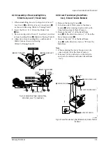
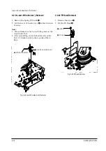
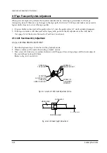
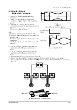
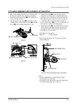
4-5-2 Linearity adjustment
(Guide roller S, T adjustment)
1. Playback the Mono Scope alignment tape
(SP mode).
2. Observe the video envelope signal on an
oscilloscope (triggered by the video switching
pulse).
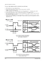
3. Make sure the video envelope waveform
(at itsminimum) meets the specification shown in
Fig. 4-5-7.
If it does not, adjust as follows :
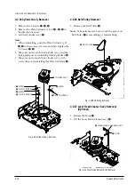
Note :
a=Maximum output of the video RF envelope.
b=Minimum output of the video RF envelope at the
entrance side.
c=Minimum output of the video RF envelope at the
center point.
d=Maximum output of the video RF envelope at the
exit side.
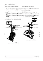
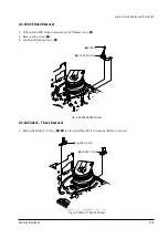
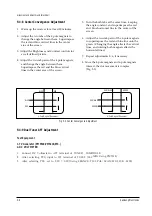
4. If the section A in Fig. 4-5-8 does not meet the
specification, adjust the guide roller S up or
down.
5. If the section B in Fig. 4-5-8 does not meet the
specification, adjust the guide roller T up or
down.
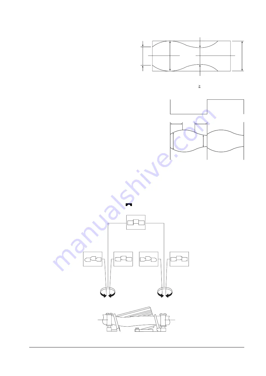
Fig. 4-5-7 Envelope Waveform Adjustment
a
a b c d
c,b,d/a
63%
b
c
d
Fig. 4-5-8 Adjustment Points
A
B
A
B
H'D SWITCHING
PULSE
ENVELOPE
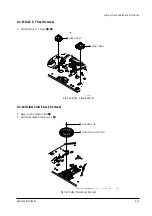
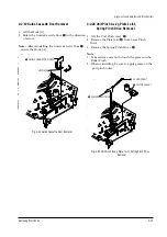
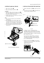
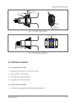
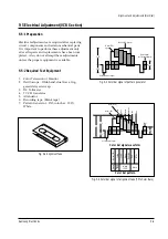
6. Play back the Mono Scope alignment tape (SP mode).
7. Connect an oscilloscope CH-1 to the Envelope and CH-2 to the HÕD SW Pulse for triggering.
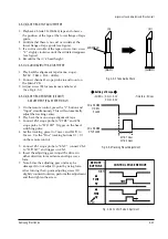
8. Turn the guide roller heads with a flat head ( ) driver to obtain a flat video RF envelope as shown in
Fig. 4-5-9.
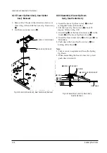
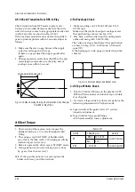
Fig. 4-5-9 Guide Roller S, T Height Adjustment
IDEAL ENVELOPE
S HEIGHT
TOO HIGH
S HEIGHT
TOO LOW
T HEIGHT
TOO LOW
T HEIGHT
TOO HIGH
GUIDE ROLLER S
GUIDE ROLLER T
Summary of Contents for TW14C52S/BWT
Page 89: ...11 Wiring Diagram 11 1 C15A Wiring Diagram Wiring Diagram Samsung Electronics 11 1 ...
Page 90: ...Wiring Diagram 11 2 Samsung Electronics 11 2 C15A Wiring Diagram ...
Page 94: ...Schematic Diagrams 12 4 Samsung Electronics 12 4 VCR POWER BLOCK ...
Page 97: ...Schematic Diagrams 12 7 Samsung Electronics 12 7 TV 3 4 RED POWER LINE BLUE SIGNAL LINE ...


