Disassembly and Reassembly
Samsung Electronics
3-19
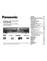
3-5-1(a) ACE HEAD HEIGHT ADJUSTMENT
1) Run the alignment tape (Color bar) in the playback
mode.
2) Observe surface of the audio head using a dental
mirror.
3) Turn screw (C) clockwise or counterclockwise until
the gap of lower tape edge and the lower edge of
the control head is about 0.25mm.
(Refer to Fig. 3-5-1 and 3-5-2)
Fig. 3-5-1 Location of ACE Head Adjustment Screw
Fig. 3-5-2 ACE Head Height Adjustment
SCREW (A)
TLIT ADJUST
X-POSITION
ADJUSTING SLIT
SCREW (C)
HEIGHT ADJUST
SCREW (D)
X-POSITION LOCKING
SCREW (B)
AZIMUTH ADJUST
0 ~ 0 .25 mm
AUDIO HEAD
VIDEO HEAD
CONTROL HEAD
3-5-1(b) ACE HEAD TILT ADJUSTMENT
1) Playback a blank tape and observe the position of
the tape at the lower flange of tape guide.
2) Confirm that there is no curl or wrinkle at the
lower flange of tape guide as shown in
Fig. 3-5-3 (B).
3) If a curl or wrinkle of the tape occurs, slightly turn
the screw (A) tilt adjust on the ACE head ass’y.
4) Reconfirm the ACE head height.
Fig. 3-5-3 Tape Guide Check
3-5-1(c) AUDIO AZIMUTH ADJUSTMENT
1) Load alignment tape (Mono scope) and playback
the NTSC : 7KHz (PAL : 6KHz) signal.
2) Connect channel-1 scope probe to audio output
test point.
3) Adjust screw (B) to achieve maximum audio level.
(See Fig. 3-5-1)
4-5-1(d) ACE HEAD POSITION (X-POINT)
ADJUSTMENT
1) See “2. Alignment and Adjustment” for ACE Head
position (X-Point) adjustment.
(A)
(B)
(BAD)
WRINKLE
(GOOD)
3-5 Tape Transport System Adjustment
When parts are replaced, perform the required
adjustments by referring to procedures for the tape
transport system. If there are any changes to the tape
path, first run a T-120 tape and make sure excessive
tape wrinkle does not occur at the tape guides.
1) If tape wrinkle is observed at the guide roller S, T,
turn the guide roller S, T until wrinkle disappears.
2) If the tape wrinkle is still observed at the tape
guide, perform the tilt adjustment of the ACE head.
(See “2. Alignment and Adjustment” of the
Service Manual for Test Point Locations.)
3-5-1 ACE Head Assembly Adjustment
Summary of Contents for TI21B4DF4X
Page 98: ...Block Diagrams 8 2 Samsung Electronics 8 2 C17A PCB Layout ...
Page 99: ...9 Wiring Diagram 9 1 C17A Wiring Diagram Wiring Diagram Samsung Electronics 9 1 ...
Page 101: ...Schematic Diagrams 10 2 Samsung Electronics 10 2 MAIN2 VOC TUNER BOX ...
Page 103: ...Schematic Diagrams 10 4 Samsung Electronics 10 4 MAIN4 SWITCHING BLOCK ...
Page 104: ...Schematic Diagrams 10 5 Samsung Electronics 10 5 MAIN5 OPTION PAL HIFI BLOCK ...
Page 105: ...Schematic Diagrams 10 6 Samsung Electronics 10 6 MAIN6 OPTION VCR SECAM BLOCK ...
Page 106: ...Schematic Diagrams 10 7 Samsung Electronics 10 7 POWER FBT ...
Page 107: ...Schematic Diagrams 10 8 Samsung Electronics 10 8 CRT ...
Page 108: ...Schematic Diagrams 10 9 Samsung Electronics 10 9 FRONT A V MASTER SW FRONT A V MASTER SW ...