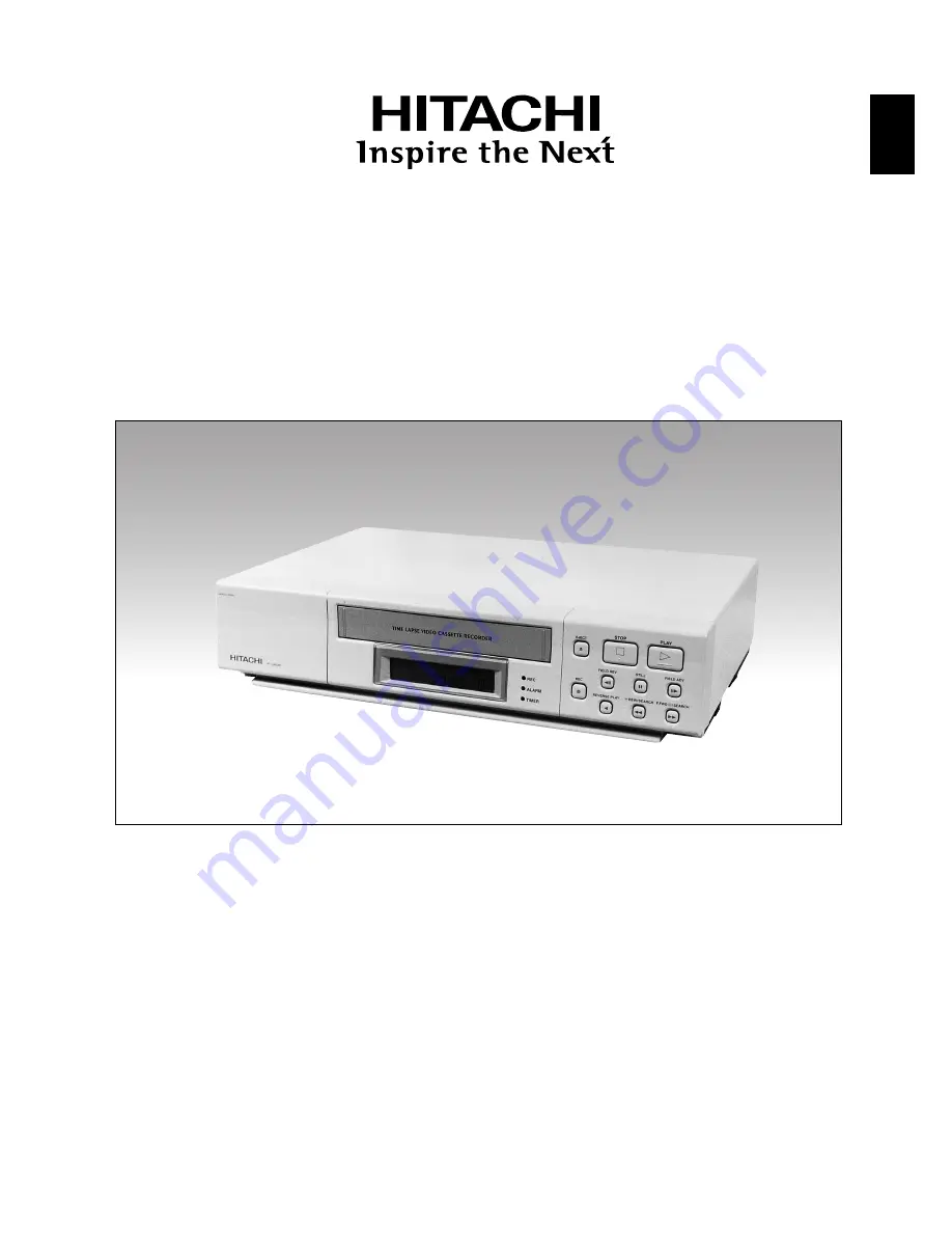
background image

ENGLISH

ENGLISH

TIME LAPSE

VIDEO CASSETTE RECORDER

VTL4024E

Instruction manual

To obtain the best performance and ensure years of
trouble-free use, please read this instruction manual
completely.

Bedienungsanleitung

Bitte lesen Sie diese Bedienungsanleitung aufmerk-
sam durch, um durch richtige Bedienung jahrelan-
gen und störungsfreien Betrieb zu gewährleisten.

Mode d’emploi

Des performances optimales et un fonctionnement
à long terme seront assurés en appliquant les
présentes instructions après avoir entièrement lu ce
mode d’emploi.

Manuale di istruzioni

Per garantire la migliore prestazione e la più lunga
durata leggere attentamente e al completo le
seguenti istruzioni.

Manual de instrucciones

Para obtener el mejor funcionamiento y asegurar
años de uso libre de problemas, lea cuidadosa-
mente este manual de instrucciones.

Gebruiksaanwijzing

Lees deze gebruiksaanwijzing aandachtig door voor
het verkrijgen van de beste prestaties en jarenlang
probleemloos gebruik.

Summary of Contents for VTL4024E

Page 1: ...mances optimales et un fonctionnement à long terme seront assurés en appliquant les présentes instructions après avoir entièrement lu ce mode d emploi Manuale di istruzioni Per garantire la migliore prestazione e la più lunga durata leggere attentamente e al completo le seguenti istruzioni Manual de instrucciones Para obtener el mejor funcionamiento y asegurar años de uso libre de problemas lea cu...

Page 2: ...hich could cause a fault Never bring a magnet or magnetized object near the VCR because it will adversely affect the per formance of the VCR Do not install the unit in an inclined position The unit is designed for operation in a horizontal position Do not place a container with water or any small metal objects on the VCR If spilled water or a metal object such as paper clip enters the VCR it could...

Page 3: ...NG THE TIME AND DATE 12 SETTING OPTIONS ITEMS 13 SUMMER TIME FUNCTION 13 SETTING THE TIMER 13 SETTING THE VCR FUNCTIONS 15 SETTING THE BUZZER 16 SETTING THE ALARM 17 ALARM MEMORY RECALL AND RESET 18 OPERATION 19 TAPE RECORDING 19 REC CHECK 19 AUTO REC CHECK 19 TIMER RECORDING 19 TAPE RECYCLE 19 ALARM RECORDING 20 MASTER SYSTEM RESET 20 PLAYBACK 20 SHARPNESS CONTROL 20 STILL PLAYBACK 20 V LOCK ADJU...

Page 4: ...ESET BUTTON Press to clear the digital counter to 0000 10 RESET BUTTONS Press these buttons at the same time to clear all microprocessor functions Press the S button to reset the system This does not erase the stored information 11 REC PLAY HOURS BUTTONS UP Press to increase hours to the next higher value DOWN Press to decrease hours to the next lower value The tape speed will be indicated as part...

Page 5: ...art recording 24 REVERSE PLAY BUTTON Press to play recorded material at the 03 speed in the reverse direction during the PLAY mode 25 REWIND VISUAL SEARCH BUTTON Press to start rewind Press this button during playback and a reverse play back picture at high speed can be seen 26 FAST FORWARD VISUAL SEARCH BUTTON Press to activate fast forward Press this button during playback and a forward play bac...

Page 6: ...NDICATOR LOCK appears when the recorder is in the security lock mode 37 HARD INDICATOR Lights when adjust the picture quality to hard during playback mode and after setting 38 SOFT INDICATOR Lights when adjust the picture quality to soft during playback mode and after setting 39 VCR MODE INDICATORS appears during recording t t appears during the rewind mode s s appears during the fast forward mode...

Page 7: ...nitor or another recorder 9 dBm 600 ohm unbalanced q ALARM IN w ALARM OUT e NC r TAPE END OUT t TAPE END RESET y WARNING OUT u NC i TIME ADJUST o CAMERA SW OUT 0 REC START IN 1 NC 2 NC 3 REMOTE IN 4 REC CHECK IN 5 GND 6 GND 6 1 5 1 4 1 3 1 2 1 1 1 0 1 9 8 6 7 5 4 3 2 1 Screwdriver Tab Wire 10mm CONNECTING WIRES 1 Strip off the wire cover by approx 10mm 2 Use a screwdriver etc to hold the tab then ...

Page 8: ...al distortion of the TIME DATE characters In multiple camera systems connect the switcher output to the Video IN BNC terminal Because mul tiple camera systems require synchronization use of cameras having line locked vertical sync or a gen locked master drive sync source is highly re commended The use of vertical interval switchers is also recommended Video Output Connect the monitor to the Video ...

Page 9: ...P IF ALARM and no alarm record ing has been made The output impedance is approx 100 ohm TAPE END RESET The TAPE END OUT can be turned off when pin t is shorted to pin 5 or 6 Note Do not apply a voltage to pin t 5 or 6 WARNING OUT When an abnormality has occurred in this VCR approx 5V is output to pin y to warn the user TIME ADJUST When two or more of this VCR model are used con nect via these term...

Page 10: ...IN Recording is started when 5 12V is applied to pin 0 REMOTE IN This VCR can be remote controlled when the follow ing circuit is connected to pin 3 The above resistance values have a tolerance of 2 REC CHECK IN Recording can be checked when pin 4 is shorted to pin 5 or 6 during recording mode The recorded material is played back for several seconds so that you can check whether recording is made ...

Page 11: ...thout its safety tab is loaded To record again on a cassette that has its safety tab removed cover the tab hole with tape In the TIMER mode the TIMER indicator will flash on and off if the cassette is inserted without its safety tab slot covered or intact TAPE LENGTH The total recording time at each of the three tape speeds depends on the length of the tape used The table below shows 1 The total r...

Page 12: ... screen when the power cord is first plugged in SELECTING A FUNCTION TO BE PROGRAMMED The program menu will always begin with the TIME DATE function followed by the CLOCK SET TIMER SELECTION MENU 1 SELECTION MENU 2 ALARM and then the ALARM MEMORY functions Although the program menu always follows this order it is possible to skip any of the available func tions during the selection process To sele...

Page 13: ...sired number appears on the monitor 12 Press the START STOP button the seconds will start counting and the clock will start CLOCK SET will flash on off again at this time 13 Press the START STOP button twice so that flashing CLOCK SET changes to a steady light 14 Press the PROGRAM button continuously so that the TIME DATE display appears Notes Perform the same procedure as when setting the time an...

Page 14: ...ssing the above buttons Note Summer time cannot be set unless TIME DATE is displayed or during the timer recording standby mode SETTING THE TIMER To set the 24 Hour On Off Timer function 1 Press the START STOP button twice so that OPTIONS flashes on off 2 Press the SET button so that the OSD TYPE set ting flashes on off 3 Press the UP or DOWN button to select the setting FULL HALF or OFF 4 Press t...

Page 15: ... 17 After setting two program event locations of MON press the SET button The two program event locations of the next day of the week flashes on off 18 Press the SET button The first program event location of the next day flashes 19 Repeat steps 12 through 16 to set the program event locations up to SUN 20 Press the START STOP button when the TIMER has been set Notes 1 Programming the TIMER functi...

Page 16: ...put during recording at 12 or a longer speed mode The pulses are output during recording in all modes The pulses are output during recording at the 03 speed mode SEARCH SPEED 3 5 7 or 9 times the normal speed You can select the visual search speed CAMERA SW 12 ALL 03 ONLY You can select the timing with which pulses are output to switch the camera SELECTION MENU 1 Format Description ELECT MODE SE E...

Page 17: ...keep sounding if recording is abnormal Buzzer will not sound even if recording is abnormal ALARM OUT ON or OFF To specify whether buzzer turns on or off when alarm is output ON OFF Buzzer will keep sounding if alarm is output Buzzer will not sound even if alarm is output SELECTION MENU 2 Format Description 4 1 Press the START STOP button The TAPE END option OFF flashes on off 2 Press the SET butto...

Page 18: ...uration set ting flashes on off 2 Press the UP or DOWN button until the desired setting appears on the monitor MANUAL 5 15 30 SEC 1 3 5 10 30 60MIN TAPE END 3 Press the SET button The record speed setting flashes on off 4 Press the UP or DOWN button until the desired setting appears on the monitor 03 12 or 24 hours 5 Press the SET button The alarm ready setting flashes on off 6 Press the UP or DOW...

Page 19: ...press the ALARM RESET button to clear the ALARM memory Notes When the ALARM RESET button is pressed once if PL is flashing PL will disappear Press the button again to clear the ALARM memory When PL is not flashing press the ALARM RESET button once to clear the ALARM memory ALARM MEMORY Display Format Description LARM M M 1 A 00 A 2 3 4 5 6 7 8 9 ORY E Displays the number of alarm inputs that have ...

Page 20: ... Note If AUTO REC CHECK ON is specified in SELECTION MENU 2 the buzzer will keep sounding when tape has not been normally recorded TIMER RECORDING This VCR can also record at any speed on TIMER command turn on off to record during any 24 hour time period To program the TIMER function refer to pages 13 and 14 To operate the TIMER recording function follow the tape recording procedure step 1 then pr...

Page 21: ... picture adjust the horizontal hold control on the monitor Adjust the SLOW TRACKING control to minimize noise when playing back at slow speed 24 hours or in the FIELD ADVANCE REVERSE mode The playback picture is not stable and has some noise at A12 or A24 mode And in these modes TRACKING control is not effective SHARPNESS CONTROL When the SHARPNESS CONTROL button is pressed during playback then wi...

Page 22: ...e 4 When the VCR finds a mark it enters normal playback mode 5 Press REW or F FWD button again to find next marked recording The recorder advances tape to the next marked position 6 Press the ALARM INDEX button again to release alarm index search Notes 1 Be careful as no alarm input can be detected for 5 seconds immediately after the visual search mode is entered by pressing the REW or F FWD butto...

Page 23: ...l equipment and connection cables Check monitor camera adjustments Adjust the TRACKING control may need to be returned to center position if previously adjust ed The TRACKING control is only active for the 03 A12 or A24 mode Replace cassette Clean video heads Remove cassette and reinsert Check the LOCK indicator on the front panel If the indicator is lit press both SET and DOWN buttons simultaneou...

Page 24: ...p 75 ohm unbalanced Video Output 1 Vp p 75 ohm unbalanced S N Ratio Video More than 42 dB 03 mode S N Ratio Audio More than 40 dB 03 mode Horizontal Resolution Colour 300 lines 03 mode Monochrome 350 lines 03 mode Audio Input 8 dBm 50 kohm unbalanced Audio Output 9 dBm 600 ohm unbalanced Audio Frequency Range 100 Hz to 8 kHz 03 mode Power AC 230V 50 Hz Power Consumption 17W Cabinet Size 435 mm W x...

Page 25: ...ming belt C C Capstan motor C R C R C Loading motor assembly R Mechanism state switch R Idler gear 1 R R Idler gear 2 R R FR gear R R JOG Gear C C R C C R C Supply slant pole C C C C C Take up slant pole C C C C C Tape guides C C C C C Tape guide line on lower cylinder C C C C C Tension band R R R FS brake C C R C C R C HC arm R Shaft and bearing of S reel table S S Shaft and bearing of T reel tab...

Page 26: ...ent switched on when it is unattended unless it is specifically stated that it is designed for unattended operation or has a standby mode Switch off using the switch on the equipment and make sure that your family know how to do this Special arrangements may need to be made for infirm or handicapped people DON T use equipment such as personal stereos or radios so that you are distracted from the r...

Page 27: ...26 ENGLISH ...

Page 28: ... ITALY Tel 39 02 487861 Tel 39 02 38073415 Servizio Clienti Fax 39 02 48786381 2 Email customerservice italy hitachi eu com HITACHI Europe AB Box 77 S 164 94 Kista SWEDEN Tel 46 0 8 562 711 00 Fax 46 0 8 562 711 13 Email csgswe hitachi eu com HITACHI EUROPE S A S Lyon Office B P 45 69671 BRON CEDEX FRANCE Tel 04 72 14 29 70 Fax 04 72 14 29 99 Email france consommateur hitachi eu com HITACHI EUROPE...

Reviews: