Samsung Electronics
12-19
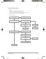
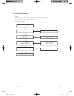
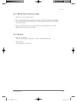
12-2-17 When the remote control is not receiving
1. Check if the connector was normally assembled.
2. Put the set in operation and check the voltage of No. 15(+) and No. 16(-) of the main PCB CN91 while operating the
remote control. When the voltage descends below 3V, the assembly module PCB is normal and the main PCB is poor.
Then replace the main PCB.
3. Replace the assembly display PCB because the module PCB is poor if the voltage between No. 15~16 of CN91
maintains 5V after the remote control starts operation.
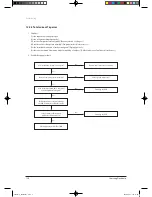
12-2-18 The others
1. AC Line Zero Cross Signal OUT
– Check the assembly condition of peripheral part of IC21, ZD201, ZD200 and D200 on the PCB.
2. Capacity miss match
– Check again the indoor unit option code.
Troubleshooting
24867A(1)_TH026EAV_1.indd 19
2006-04-03 ソタタ・9:49:25

