background image


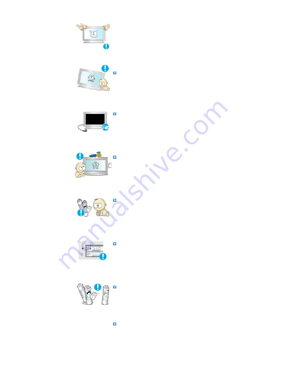
Place the product out of children’s reach, as they could damage by 
hanging onto it. 

z

A falling product may cause injury to the person or even fatality.  


When not using the product for an extended period of time, keep the 
product unplugged. 

z

Otherwise, this may cause heat emission from the accumulated dirt or 
degraded insulation, causing electric shock or fire.  


Do not place your children's favorite toys or any other objects of 
interest on the product. 

z

Children may try to climb on the product to retrieve an object. The product 
could fall, causing injury or even fatality.  


When removing batteries from the remote control, be careful that 
they are not swallowed by children. keep the batteries out of 
children's reach.

z

If the batteries are swallowed, see a doctor immediately.  


When replacing batteries, place the batteries in the c/- 
polarity position as indicated on the battery holder. 

z

The incorrect polarity may cause a battery to break or leak and may cause 
fire, injury, or contamination (damage).  


Use only specified standard batteries. Do not use new and used 
batteries together. 

z

This may cause a battery to break or leak and may cause fire, injury, or 
contamination (damage).  


The batteries (and rechargeable batteries) is not ordinary refuse and 
must be returned for recycling purposes. The customer is 
responsible for returning the used or rechargeable batteries for 
recycling purposes as the consumer. 

z

The customer can return used or rechargeable batteries to a nearby public 

Summary of Contents for SyncMaster 700TSn

Page 1: ...n Safety Instructions Introduction Connections Using the Software Adjusting the LCD Display Troubleshooting Specifications Information Appendix 2008 Samsung Electronics Co Ltd All rights reserved Model SyncMaster 700TSn 820TSn Select Language ...

Page 2: ...nt to read and understand at all times Do not disassemble Disconnect the plug from the outlet Do not touch Ground to prevent an electric shock Power When not used for an extended period of time set your computer to DPM If using a screen saver set it to active screen mode The images here are for reference only and are not applicable in all cases or countries Do not use a damaged or loose plug z Thi...

Page 3: ...sed by the separation and may damage the LCD Display Do not use the power cord when the connector or plug is dusty z If the connector or plug of the power cord is dusty clean it with a dry cloth z Using the power cord with a dusty plug or connector may cause electric shock or fire To disconnect the apparatus from the mains the plug must be pulled out from the mains socket therefore the mains plug ...

Page 4: ... the person carrying it Do not place the product on an unstable or small surface area z Place the product on an even and stable surface as the product may fall and cause harm to someone walking by specifically children Do not place the product on the floor z Take care as someone specifically children may trip over it TO PREVENT THE SPREAD OF FIRE KEEP CANDLES OR OTHER OPEN FLAMES AWAY FROM THIS PR...

Page 5: ...keep it away from the wall for ventilation purposes z Poor ventilation may cause an increase in the internal temperature of the product resulting in a shortened component life and degraded performance Keep the plastic packaging bag out of children s reach z The plastic packaging bag may cause suffocation if children play with it Clean When cleaning the LCD Display case or the surface of the TFT LC...

Page 6: ...particular if there is any unusual sound or smell coming from the LCD Display unplug it immediately and contact an authorized dealer or the Service Center z This may cause electric shock or fire Keep the product away from places exposed to oil smoke or moisture do not install inside a vehicle z This may cause a malfunction electric shock or fire z In particular avoid operating the LCD Display near...

Page 7: ...CD Display z This may cause a malfunction electric shock or fire z If a foreign substance enters the LCD Display unplug the power cord and contact the Service Center Keep the product away from combustible chemical sprays or inflammable substances z This may cause an explosion or fire Never insert anything metallic into the LCD Display openings z This may cause electric shock fire or injury Do not ...

Page 8: ...at least a five minute break after every hour of using the LCD Display Do not install the product on an unstable uneven surface or a location prone to vibrations z Dropping the product may cause damage to the product or the person carrying it Using the product in a location prone to vibrations may shorten the lifetime of the product or may cause the product to catch fire When moving the LCD Displa...

Page 9: ...hey are not swallowed by children keep the batteries out of children s reach z If the batteries are swallowed see a doctor immediately When replacing batteries place the batteries in the correct polarity position as indicated on the battery holder z The incorrect polarity may cause a battery to break or leak and may cause fire injury or contamination damage Use only specified standard batteries Do...

Page 10: ...to the current consumption in the Rated Capacities table and use a multi plug with the permitted current specifications greater than the total current consumption of the products connected to it z When using a dedicated power extension cable use a high capacity power cable Use a power cable with a permitted current of 12 5 A or more Rated Current of the Power Plug Cord Appliance Coupler z Use a po...

Page 11: ...886 1 59 1 8 W max output power 90 V 60 Hz 10 483 945 1 59 1 8 W max output power 100 V 60 Hz 9 281 933 1 59 1 8 W max output power 240 V 60 Hz 3 754 889 1 59 1 8 W max output power 254 V 60 Hz 3 572 886 1 59 1 8 W max output power 1995 2008 SAMSUNG ALL Rights Reserved ...

Page 12: ...ems are included with your LCD Display If any items are missing contact your dealer Contact a local dealer to buy optional items Note This stand is not for the Floor Standing Type LCD Display Manuals Quick Setup Guide Warranty Card Not available in all locations User s Guide MDC Software Cables D Sub Cable Power Cord Safety Instructions Introduction Package Contents Your LCD Display Mechanical Lay...

Page 13: ...and exits from the menu or closes the adjustment menu 2 Navigate buttons Up Down buttons Moves from one menu item to another vertically or adjusts selected menu values 3 Adjust buttons Left Right buttons Volume buttons Moves from one menu item to another horizontally or adjusts selected menu values Adjusts the audio volume 4 ENTER Activates a highlighted menu item 5 SOURCE Switches from PC mode to...

Page 14: ...CD Display On Off 8 Brightness Sensor The product s Brightness Sensor function automatically detects the surrounding brightness using a brightness sensor and adjusts its brightness accordingly 9 Power indicator Shows PowerSaver mode by blinking green 10 Remote Control Sensor Aim the remote control towards this spot on the LCD Display Note See PowerSaver described in the manual for further informat...

Page 15: ...MI Connect the HDMI terminal at the back of your monitor to the HDMI terminal of your digital output device using a HDMI cable 6 DVI PC HDMI IN RGB PC Video Connection Terminal Using a D Sub Cable 15 pin D Sub PC mode Analog PC 7 DVI PC HDMI IN DVI HDCP PC Video Connection Terminal Using a DVI Cable DVI D to DVI D DVI mode Digital PC 8 COMPONENT AUDIO IN L AUDIO R Component Audio Connection Termin...

Page 16: ...Output AUDIO OUT is the terminal for sound output of PC DVI or BNC 17 LAN LAN Connection Terminal 18 USB USB Connection Terminal Keyboard Mouse Mass Storage Device Compatible Note The number of LCD Displays that can be connected to loopout may differ depending on the cables signal source etc With cables where there is no degradation or signal source up to ten LCD Displays can be connected Note See...

Page 17: ...ick Launch Button 3 MDC MDC Quick Launch Button 4 LOCK Activates or deactivates all function keys on both the remote control and the LCD Display except for the Power and LOCK buttons 5 MagicInfo buttons Used for MagicInfo Alphanumeric Used to enter the Internet address DEL Functions as the backspace SYMBOL Used to enter the symbols O_ ENTER Used to enter values 6 100 Press to select channels over ...

Page 18: ...hanging the resolution in the control panel auto function is performed 14 ENTER PRE CH Returns to the immediately previous channel This fuction does not work for this monitor 15 CH P In TV mode selects TV channels This fuction does not work for this monitor 16 SOURCE Changes the video source 17 INFO The current picture information is displayed in the top left corner of the screen 18 EXIT Exits fro...

Page 19: ..._Mode Default FM Stereo Mono Mono Manual Change Stereo Mono Stereo SAP Mono SAP Mono 26 PIP Every time you press the button a PIP screen appears 27 SOURCE Changes the source of the PIP window signal 28 SWAP Swaps the contents of the PIP and main image The image in the PIP window will appear on the main screen and the main screen image will appear in the PIP window 29 SIZE Switches the PIP Picture ...

Page 20: ...Mechanical Layout Monitor Head Speaker Installation VESA Bracket Wall Bracket Installation 1 Mechanical Layout 2 Monitor Head ...

Page 21: ...ormation Please contact your nearest Samsung Distributor to place an order After your order is placed installation professionals will visit you and install the bracket z At least 2 persons are needed in order to move the LCD Monitor z Samsung is not responsible for any product damage or any injury caused by installation at customer s discretion Dimensions ...

Page 22: ...tallation is done by the customer z This product is for installing on cement walls The product may not stay in place when installed on plaster or wood Components Only use the components and accessories shipped with the product Wall Bracket 1 Hinge Left 1 Right 1 Plastic Hanger 4 Screw A 11 Screw B 4 Anchor 11 Wall Bracket Assembly Insert and tighten the Captive Screw in the direction of the arrow ...

Page 23: ...he length A Length between the two locking holes Check the installation diagram and mark the drill points on the wall Use the 5 0 mm bit to drill holes deeper than 35 mm Fix each anchor in the corresponding hole Match each of the brackets and hinge holes to the corresponding anchor holes and insert and tighten the 11 screws A To mount the product on the wall bracket The shape of the product may va...

Page 24: ...fixed to the wall or the product may not stay in place after installation Tighten the 4 screws in step 2 plastic hanger screw B to the rear holes of the product Remove safety pin 3 and insert the 4 product holders into the corresponding bracket holes 1 Then place the product 2 so that it is firmly fixed to the bracket Make sure to re insert and tighten the safety pin 3 to securely hold the product...

Page 25: ... product at the top in the center and pull it forward direction of the arrow to adjust the angle 3 You can adjust the bracket angle between 2 and 15 Make sure to use the top center and not the leftor the right side of the product to adjust the angle ...

Page 26: ...Mechanical Layout Monitor Head Speaker Installation VESA Bracket Wall Bracket Installation 1 Mechanical Layout 2 Monitor Head ...

Page 27: ...ormation Please contact your nearest Samsung Distributor to place an order After your order is placed installation professionals will visit you and install the bracket z At least 2 persons are needed in order to move the LCD Monitor z Samsung is not responsible for any product damage or any injury caused by installation at customer s discretion Dimensions ...

Page 28: ...tallation is done by the customer z This product is for installing on cement walls The product may not stay in place when installed on plaster or wood Components Only use the components and accessories shipped with the product Wall Bracket 1 Hinge Left 1 Right 1 Plastic Hanger 4 Screw A 11 Screw B 4 Anchor 11 Wall Bracket Assembly Insert and tighten the Captive Screw in the direction of the arrow ...

Page 29: ...he length A Length between the two locking holes Check the installation diagram and mark the drill points on the wall Use the 5 0 mm bit to drill holes deeper than 35 mm Fix each anchor in the corresponding hole Match each of the brackets and hinge holes to the corresponding anchor holes and insert and tighten the 11 screws A To mount the product on the wall bracket The shape of the product may va...

Page 30: ...fixed to the wall or the product may not stay in place after installation Tighten the 4 screws in step 2 plastic hanger screw B to the rear holes of the product Remove safety pin 3 and insert the 4 product holders into the corresponding bracket holes 1 Then place the product 2 so that it is firmly fixed to the bracket Make sure to re insert and tighten the safety pin 3 to securely hold the product...

Page 31: ... product at the top in the center and pull it forward direction of the arrow to adjust the angle 3 You can adjust the bracket angle between 2 and 15 Make sure to use the top center and not the leftor the right side of the product to adjust the angle ...

Page 32: ...l not be responsible for damages caused by using a base other than those specified Installing the Semi Stand Left stand Right stand Caution Make sure to install the stand with the Caution label folded backwards Caution The resolution may differ for each product model For information on the optimal resolution refer to the user manual Connecting the LCD Display Safety Instructions Introduction Conne...

Page 33: ...t the power cord for your LCD Display to the power port on the back of the LCD Display Trun on the power switch 2 There are 3 ways to connect the D sub to your LCD Display Choose one of the following 2 1 Using the D sub Analog connector on the video card Connect the D sub to the 15 pin RGB port on the back of your LCD Display and the 15 pin D sub Port on the computer 2 2 Using the DVI Digital conn...

Page 34: ...as VCRs or Camcorders are connected via the AV IN VIDEO or AV IN S VIDEO of the LCD Display using an S VHS or BNC cable 2 Connect the Audio L and Audio R terminals of a VCR or Camcorders to the LCD Display s AV AUDIO IN L AUDIO R using audio cables Note Select AV or S Video for a connected VCR or Camcorder using the SOURCE button on the front of the LCD Display or on the remote control Then start ...

Page 35: ...serted Note A component cable is optional For an explanation of Component video consult your DVD manual Connecting a Camcorder 1 Locate the A V output jacks on the camcorder They are usually found on the side or back of the camcorder Connect a set of audio cables between the AUDIO OUTPUT jacks on the camcorder and the AV AUDIO IN L AUDIO R on the LCD Display 2 Connect a video cable between the VID...

Page 36: ...cable between the BNC COMPONENT IN PR Y PB port on the LCD Display and the PR Y PB jacks on the Set Top Box 2 Connect a set of audio cables between the COMPONENT AUDIO IN L AUDIO R on the LCD Display and the AUDIO OUT jacks on the Set Top Box Note Select Component for the connection to a DTV Set Top Box using the SOURCE button on the front of the LCD Display or on the remote control Note For an ex...

Page 37: ...ugh the REMOTE OUT terminal You can control a device by allowing it to receive remote control signals from other devices through the REMOTE IN terminal Note Restrictions Available only if other devices support the wired remote control I O terminals Connecting HDMI Note Input devices such as digital DVD are connected to the HDMI IN terminal of the monitor using the HDMI cable Note You cannot connec...

Page 38: ...ks of an RCA to stereo for PC cable to the same colored audio output terminals of the digital output device and connect the opposite jack to the HDMI PC DVI D AUDIO IN terminal of the monitor Connecting a LAN Cable 1 Connect the LAN cable Connecting a USB device 1 You can connect USB devices such as a mouse or keyboard 1995 2008 SAMSUNG ALL Rights Reserved ...

Page 39: ... Internet web site shown here Internet web site http www samsung com Worldwide Installing the Monitor Driver Automatic 1 Insert CD into the CD ROM drive 2 Click Windows 3 Choose your monitor model in the model list then click the OK button 4 If you can see following message window then click the Continue Anyway button Then click OK button Microsoft Windows XP 2000 Operating System Note This monito...

Page 40: ...lick Properties in the Monitor tab If the Properties button is deactivated it means the configuration for your monitor is completed The monitor can be used as is If the message Windows needs is displayed as shown in the figure below click Continue 6 Click Update Driver in the Driver tab Note This monitor driver is under certifying MS logo and this installation doesn t damage your system The certif...

Page 41: ...ers on my computer 8 Click Have Disk and select the folder for example D Drive where the driver setup file is located and click OK 9 Select the model that matches your monitor from the list of monitor models on the screen and click Next 10 Click Close Close OK OK on the following screens displayed in sequence ...

Page 42: ... Appearance and Themes icon 3 Click Display icon and choose the Settings tab then click Advanced 4 Click the Properties button on the Monitor tab and select Driver tab 5 Click Update Driver and select Install from a list or then click Next button 6 Select Don t search I will then click Next and then click Have disk ...

Page 43: ...ation is completed Note This monitor driver is under certifying MS logo and this installation doesn t damage your system The certified driver will be posted on Samsung Monitor homepage http www samsung com Microsoft Windows 2000 Operating System When you can see Digital Signature Not Found on your monitor follow these steps 1 Choose OK button on the Insert disk window 2 Click the Browse button on ...

Page 44: ...he monitor that corresponds to the one you connected to your computer and click OK 11 Continue choosing Close button and OK button until you close the Display Properties dialogue box Microsoft Windows NT Operating System 1 Click Start Settings Control Panel and then double click Display icon 2 In Display Registration Information window click Settings Tab and then click All Display Modes 3 Select a...

Page 45: ...C a standard of serial communication is used for the communication between a PC and a display Therefore a serial cable should be connected between the serial port on a PC and the serial port on a display Main Screen Click Start Program Samsung MDC System to start the program Select a set to see the volume of the selected set within the slider ...

Page 46: ...ng for the PC Serial Port can change The original value is COM1 5 Click Select all or Clear to select or clear all displays 6 Use Grid to view brief information on selected display 7 Select a display from Display Selection 8 Use Control Tools to control displays Note The remote control Enable Disable function operates whether or not the power is On Off and this applies to all displays connected to...

Page 47: ...n the Port Selection Menu 3 If the exact port name that is connected to the LCD Display using a serial cable is not selected communication will be unavailable 4 The selected port is stored in the program and used for the next program as well Power Control 1 Click Power Control of the main icons and the Power Control screen appears ...

Page 48: ...sary to Power Control 1 Power Status 2 Input 3 Image Size 4 On Timer 5 Off Timer 2 Use the Select All button or Check Box to choose a display to control Power Control allows controlling some of the functions of the selected display 1 Power On Off ...

Page 49: ...electing one set at a time turn on the Mute function for the selected set The Mute function is disabled automatically when you adjust the volume level The values return to the default settings when you undo the selections or choose Select All The Power Control feature is available for all displays The Volume Control and Mute features are available only for the displays whose power status is ON Inp...

Page 50: ...ideo Changes the Input Source of the selected display to S Video 8 Component Changes the Input Source of the selected display to Component 9 MagicInfo The Input source of MagicInfo works only on MagicInfo model 10 HDMI Changes the Input Source of the selected display to HDMI 11 Channel Channel arrow appears when the Input Source is TV TV Source can be selected only in products with TV and controll...

Page 51: ...hen you click Image Size the PC Source tab first appear The Image Size Control button controls Image Size available for PC BNC DVI 6 Video Source Click the Video Source tab to control Image Size for respective Input Source The Input source of MagicInfo works only on MagicInfo model The Input source of TV works only on TV model Image Size Control is available only for the displays for which power s...

Page 52: ... source 3 Switch Image Size of the selected display randomly Note Auto Wide Zoom1 and Zoom2 are not available for selection when the input signal type for Component and DVI HDCP is 720p or 1080i The Auto Wide mode is available only for TV AV and S Video The Input source of MagicInfo works only on MagicInfo model The Input source of TV works only on TV model The Image Size Control feature is availa...

Page 53: ...ff Time Setup of the selected display 4 Shows the On Time settings 5 Shows the Off Time settings The Input source of MagicInfo works only on MagicInfo model The Input source of TV works only on TV model Time Control is available only for the displays for which the power status is ON At On Time Setup TV Source functions only for TV Model At On Time Setup MagicInfo Source functions only for MagicInf...

Page 54: ...Small 5 Double 1 Turns on the PIP of the selected display and changes the size to Double 1 6 Double 2 Turns on the PIP of the selected display and changes the size to Double 2 7 Double 3 Picture By Picture Turns on the PBP of the selected display and changes the size to Double 3 The Input source of MagicInfo works only on MagicInfo model The Input source of TV works only on TV model PIP Size can b...

Page 55: ...AV 6 S Video Changes the source of the PIP of the selected display to S Video 7 Component Changes the source of the PIP of the selected display to Component 8 HDMI Changes the source of the PIP of the selected display to HDMI Note Some of the PIP Sources may not be available for selection depending on the input source type of the Main Screen The Input source of MagicInfo works only on MagicInfo mo...

Page 56: ...ay 4 Sharpness Adjusts Sharpness of the selected display 5 Color Adjusts Color of the selected display 6 Tint Adjusts Tint of the selected display Available only for NT 7 Color Tone Adjusts the Color Tone for the selected display 8 Color Temp Adjusts the Color Temp for the selected display 9 Brightness Sensor Adjusts the Brightness Sensor for the selected display 10 Dynamic Contrast Adjusts the Dy...

Page 57: ...ness Adjusts Brightness for the selected display 4 Red Adjusts red Color of the selected display Available only for NT 5 Green Adjusts green Color of the selected display Available only for NT 6 Blue Adjusts blue Color of the selected display Available only for NT 7 Color Tone Adjusts the Color Tone for the selected display 8 Color Temp Adjusts the Color Temp for the selected display 9 Brightness ...

Page 58: ...ode to CUSTOM 1 Audio Controls audio settings for all input sources 2 Bass Adjusts Bass of the selected display 3 Treble Adjusts Treble of the selected display 4 Balance Adjusts Balance of the selected display 5 SRS TS XT SRS TS XT Sound ON OFF of the selected display 6 Sound Select Select either Main or Sub when PIP is On The Input source of MagicInfo works only on MagicInfo model The Input sourc...

Page 59: ...tion Adjusts Position of the selected display 5 Auto Adjustment Self Adjust to the incoming PC signal The Input source of MagicInfo works only on MagicInfo model The Input source of TV works only on TV model Settings Control is available only for the displays for which the power status is ON Maintenance Lamp Control 1 Click on the Maintenance icon in the Main Icon column to display the Maintenance...

Page 60: ...mp Control 3 Manual Lamp Control Allows you to adjust the backlight of the selected display regardless of the time The Auto Lamp Control automatically turns off if you adjust using the Manual Lamp Control The Maintenance Control feature is available only for the displays whose power status is ON The Input source of MagicInfo works only on MagicInfo model The Input source of TV works only on TV mod...

Page 61: ...ixel Bar and Eraser by Screen Type The Input source of MagicInfo works only on MagicInfo model The Input source of TV works only on TV model Setting Second you can set to 1 2 3 4 5 for Scroll Type and to 10 20 30 40 50 for Pixel Bar and Eraser Type The Maintenance Control feature is available only for the displays whose power status is ON Maintenance Video Wall 1 Click on the Maintenance icon in t...

Page 62: ...by pressing a number in the selected mode z The MDC program supplied by Samsung supports up to 5x5 LCD Displayes 3 On Off Turns on off the Video Wall function of the selected display 4 Format The format can be selected to see a divided screen z Full z Natural You may not operate this function in MagicInfo The Input source of TV works only on TV model The Maintenance Control function is available o...

Page 63: ...me is showing Apply current time to synchronize the display clocks 5 The remote may not function properly when you turn off the remote Function disconnect the RS 232C cable or exit the program in an Irregular manner Rerun the program and turn the remote function again to Restore normal functions Note This program may malfunction due to problems in communication circuits or interference from electr...

Page 64: ...before calibration otherwise the touchscreen won t work The setting of multi touchscreens at the same PC comprising of Steps the butt mark will appear on the center of each monitor screen in master slave sequence operated by program after user clicks Select Monitor If does so use may click the center of the butt mark so as to acknowledge the mounted touchscreen If there is no information of touchs...

Page 65: ...done by clicking on 4 calibration points so that user only clicks the center of the bull s eye in sequence If failing to hit the bull s eye user may move the pointer or fingers to the center of it again and lift based on the utilization of Click on Release when calibration Press Esc button to exit calibration After calibration the recalibrate OK cancel buttons will show up ReCalibrate means recali...

Page 66: ...lower the pop up time Delay unit is millisecond The area is used for adjusting the jitter range of the touch surface within limit of error unit pixel The higher the value the wider the jitter range Right Click menu will pop up so long as the finger contacts the screen for a while within the range 7 Enable Double Click Same as the function of Mouse Double Click Double click on the same setting area...

Page 67: ...e function of Enable Delay Touch will do the work to prevent the false touch Instructions see Attachment Setting of touchscreen in strong light rain and snow condition Serial port Settings 1 Installation of the driver of serial port finished choose start All Programs IRTOUCHSYSTEMS Serial Port Settings In the list show both the name of IR touch device installed and the number of the serial ports Y...

Page 68: ...me as the function of Mouse Double Click Double click on the same setting area of objects in a short time may open up the object Speed unit is at 500 to 550 Area unit is 32px 3 Drag Delay The function show the amount of millisecond Drag Delay will take to be enabled after you click that Drag Delay may be adjuste d to the correct value if theobject can not be precisely selected or if jitter happens...

Page 69: ...ow many times you click to approach the setting value within 3 seconds Then driver will install the function of False touch rejection where quick click or scratch will be considered void except the touch point on the active area for quite a while 3 Leave count False touch rejection is no longer effective when the click times within 5 seconds is less than the setting number ...

Page 70: ...n the remote control is the SOURCE button Note PIP turns off when the LCD Display is switched to an external source For PC and DVI this is deactivated if the cable is disconnected PIP When external AV devices such as VCRs or DVDs are connected to the LCD Display PIP allows you to watch video from those devices in a small window super imposed on the PC Video signal Off On Note More than one PIP can...

Page 71: ...ntrol is the SWAP button 4 Size MENU ENTER ENTER ENTER ENTER Changes the Size of the PIP window The direct button on the remote control is the SIZE button 5 Position MENU ENTER ENTER ENTER ENTER Changes the Position of the PIP window 6 Transparency MENU ENTER ENTER ENTER ENTER Adjusts the Transparency of PIP windows High Medium Low Opaque Note If you select in Size Position and Transparency will n...

Page 72: ...figured values may not be comfortable for your eyes depending on your taste If this is the case Adjusts the brightness and contrast by using the OSD menu The direct button on the remote control is the M B button Custom MENU ENTER ENTER ENTER ENTER By using the on screen menus the contrast and brightness can be changed to your personal preference 1 Contrast Adjusts the Contrast 2 Brightness Adjusts...

Page 73: ...ng the Fine adjustment use the Coarse adjustment and then use Fine again Available in PC BNC mode only 1 Coarse MENU ENTER ENTER ENTER ENTER Removes noise such as vertical stripes Coarse adjustment may move the screen image area You may relocate it to the center using the horizontal control menu 2 Fine MENU ENTER ENTER ENTER ENTER Removes noise such as horizontal stripes If the noise persists even...

Page 74: ... Brightness Adjusts the Brightness of the PIP window on the screen 3 Sharpness Adjusts the difference between the lightest and darkest areas of the PIP window 4 Color Adjusts the Color of the PIP window on the screen 5 Tint Adds a natural tone to the PIP window You can view a picture from AV S Video through the PIP screen in PC BNC and DVI mode Operates only if the video signal is NTSC Available M...

Page 75: ...V and S Video mode Operates only if the video signal is NTSC Color Tone MENU ENTER ENTER ENTER The color tones can be changed The individual Color components are also user adjustable 1 Off 2 Cool2 3 Cool1 4 Normal 5 Warm1 6 Warm2 Note If you set the Color Tone to Cool1 Cool2 Normal Warm1 or Warm2 the Color Temp function is disabled Color Temp MENU ENTER ENTER ENTER Color temp is a measure of the w...

Page 76: ...TER ENTER ENTER Turns the Digital Noise Reduction feature Off On The Digital Noise Reduction feature allows you to enjoy clearer and crisper images 1 Off 2 On Film Mode MENU ENTER ENTER ENTER Turns Film Mode Off On The Film Mode feature offers you a theater quality viewing experience i Not available in HDMI Mode 1 Off 2 On PIP Picture MENU ENTER ENTER ENTER ENTER ENTER Adjusts the PIP Screen Setti...

Page 77: ...y audio 2 Treble Emphasizes high frequency audio 3 Balance Allows you to Adjusts the sound balance between the left and right speakers You can hear the sound even when sound value is set to 0 Note If you adjust picture using Sound Custom function Sound Mode will turn to Custom mode Auto Volume MENU ENTER ENTER ENTER Reduces the difference in volume control between broadcasters 1 Off 2 On SRS TS XT...

Page 78: ...r On Timer and Off Timer 1 Clock Set MENU ENTER ENTER ENTER ENTER Current Time Setting 2 Sleep Timer MENU ENTER ENTER ENTER ENTER ENTER Turns the LCD Display off automatically at certain times Off 30 60 90 120 150 180 3 On Timer MENU ENTER ENTER ENTER ENTER Turns the LCD Display on automatically at a preset time Controls the mode and the volume level at the time the LCD Display turns on automatica...

Page 79: ...oration etc depending on the external device connected In this case adjust the screen quality of your TV by configuring the HDMI black level 1 Normal 2 Low Video Wall A Video Wall is a set of video screens connected together so that each screen shows a part of the whole picture or where the same picture is repeated on each screen When the Video Wall is on you can adjust the Video Wall screen setti...

Page 80: ... mode Safety Screen The Safety Screen function is used to prevent afterimages that may appear when a still picture is displayed on the screen over a long time The Screen Scroll function scrolls the screen for the specified period of time This function is not available when the power is turned off 1 Safety Screen MENU ENTER ENTER ENTER ENTER Determines whether to turn the Screen Scroll function Off...

Page 81: ...ter lamp in order to reduce energy consumption Note This function does not operate when Dynamic Contrast is set to On in AV S Video Component modes Power On Adjustment MENU ENTER ENTER ENTER ENTER Adjusts the Power On time for the screen Caution Set the Power On time to be loger to avoid overvoltage FAN MENU ENTER ENTER ENTER Adjusts the FAN 1 Normal 2 Pivot Note When pivoting your monitor make su...

Page 82: ...ly a SET where the ID corresponds to the transmitter setting becomes activated Direct Functions Available Modes PC BNC DVI AV S Video Component HDMI MagicInfo MagicInfo Moves to the MagicInfo OSD screen MDC Moves to the Multi Control OSD screen LOCK Sets the Safety Lock function 1 Lock On It will be locked 2 Lock Off It will be unlocked Note When setting the Lock function you can only operate the ...

Page 83: ...stem Do not unplug the LAN cable used by an USB device ex video display Otherwise the program MagicInfo may stop To access other sources press the SOURCE button in MagicInfo The preset password for the LCD Display is 000000 The server program s Power On option works only if the LCD Display s power is completely shut off Please make sure not to use the Power On option when the LCD Display is in the...

Page 84: ...double click the Magicinfo icon on the window desktop The icon will appear 6 Right click on the Magicinfo pro icon the image will be inserted and select Program player from the displayed menu 7 The Player screen of Magicinfo pro is displayed Note To finish the MagicInfo press ALT F12 To setup MagicInfo on a Windows screen a keyboard and mouse are required To setup MagicInfo on a Windows screen ref...

Page 85: ...educed picture 6 Close Closes the image control Menu Music The MP3 file format is supported Movie The MPEG1 WMV file format are supported 1 Play Plays a movie file 2 Full Size Plays a movie file in full screen OFFICE HTML PPT Power Point DOC MS Word XLS MS Excel PDF HTML HTM files are displayed Install the proper viewer freeware program to see the MS Office Word Excel Power Point or PDF doucuments...

Page 86: ...vable disks 6 Play Option You can set the repeat play and screen settings Repeat Determines the repeat option for playing movies and music None Select No Repeat to play a movie or tune in the list only once File Repeat Select Repeat File to play a movie or tune in the list repeatedly List Repeat Select Repeat List to play movies or tunes in the list in sequence repeatedly Rotation Sets the picture...

Page 87: ...l is detected While in the Self Test mode the LED power indicator remains green and the figure moves around on the screen 4 Turn off your LCD Display and reconnect the video cable then turn on both your computer and the LCD Display If your LCD Display screen remains blank after using the previous procedure check your video controller and computer system your LCD Display is functioning properly Not...

Page 88: ...re properly connected to the computer 2 Check if the computer beeps more than 3 times when booting If it does request an a service for the main board of the computer 3 If you installed a new video card or if you assembled the PC check if you installed the Adaptor video 4 Check if the scanning ratio of the video screen is set to between 50 Hz 85 Hz Do not exceed 60Hz when using the maximum resoluti...

Page 89: ...c z Set the resolution and frequency to the recommended ranges The picture image is unstable and shakes Ghost images are shown in the picture z Check if the resolution and frequency set for the computer video card falls in the range supported by the LCD Display If not reset them referring to the current Information under the LCD Display menu and Preset Timing Modes The image is too light or too da...

Page 90: ...is on in the vicinity Problems related to MagicInfo Note Making a Bootable USB Flash Disk Problems Solutions Making a Bootable USB Flash Disk 1 You can turn a common 512 MB or bigger USB storage media into a bootable disk using a USB bootable disk creation tool For example the HP USB Disk Storage Format Tool 2 Copies the OS ghost image and executables to your USB disk 3 Enter the BIOS menu of your...

Page 91: ...ndows ME 2000 Set the resolution at the Control Panel Display Screen Saver Set the function in the BIOS SETUP of the computer Refer to the Windows Computer Manual How can I clean the outer case LCD Panel Disconnect the power cord and then clean the LCD Display with a soft cloth using either a cleaning solution or plain water Do not leave any detergent or scratches on the case Do not let any water ...

Page 92: ... Separate H V sync Composite SOG TTL level V high 2 0 V V low 0 8 V Maximum Pixel Clock 165 MHz Analog Digital Power Supply AC 100 240 V 10 50 60 Hz Signal Cable 15pin to 15pin D sub cable Detachable DVI D to DVI D connector Detachable Dimensions WxHxD 1668 x 989 x 154 mm 65 7 x 38 9 x 6 1 inch Without Stand 1668 x 1094 x 500 mm 65 7 x 43 1 x 19 7 inch With Stand Weight 122 kg 269 0 lbs With Stand...

Page 93: ...ble storage can be supported Contents Photo Supported File Format BMP JPEG 2274x1704 or less Music Supported File Format MP3 Sound bandwidth 50 Hz to 15 kHz Movie z MPEG1 WMV z Max 1280 x 720 30 fps File MS Office Word Excel Power Point HTML PDF z Some files may not be supported depending on the format or the version z Install the proper viewing freeware program to see MS Office Word Excel Power P...

Page 94: ...72 809 31 500 VESA 640 x 480 37 500 75 000 31 500 VESA 800 x 600 35 156 56 250 36 000 VESA 800 x 600 37 879 60 317 40 000 VESA 800 x 600 48 077 72 188 50 000 VESA 800 x 600 46 875 75 000 49 500 VESA 1024 x 768 48 363 60 004 65 000 VESA 1024 x 768 56 476 70 069 75 000 VESA 1024 x 768 60 023 75 029 78 750 VESA 1152 x 864 67 500 75 000 108 000 VESA 1280 x 960 60 000 60 000 108 000 VESA 1280 x 1024 63...

Page 95: ...e H V sync Composite SOG TTL level V high 2 0 V V low 0 8 V Maximum Pixel Clock 165 MHz Analog Digital Power Supply AC 100 240 V 10 50 60 Hz Signal Cable 15pin to 15pin D sub cable Detachable DVI D to DVI D connector Detachable Dimensions WxHxD 1915 x 1125 x 155 mm 75 4 x 44 3 x 6 1 inch Without Stand 1915 x 1230 x 500 mm 75 4 x 48 4 x 19 7 inch With Stand Weight 140 kg 308 6 lbs With Stand VESA M...

Page 96: ...ble storage can be supported Contents Photo Supported File Format BMP JPEG 2274x1704 or less Music Supported File Format MP3 Sound bandwidth 50 Hz to 15 kHz Movie z MPEG1 WMV z Max 1280 x 720 30 fps File MS Office Word Excel Power Point HTML PDF z Some files may not be supported depending on the format or the version z Install the proper viewing freeware program to see MS Office Word Excel Power P...

Page 97: ... 72 809 31 500 VESA 640 x 480 37 500 75 000 31 500 VESA 800 x 600 35 156 56 250 36 000 VESA 800 x 600 37 879 60 317 40 000 VESA 800 x 600 48 077 72 188 50 000 VESA 800 x 600 46 875 75 000 49 500 VESA 1024 x 768 48 363 60 004 65 000 VESA 1024 x 768 56 476 70 069 75 000 VESA 1024 x 768 60 023 75 029 78 750 VESA 1152 x 864 67 500 75 000 108 000 VESA 1280 x 960 60 000 60 000 108 000 VESA 1280 x 1024 6...

Page 98: ...tain it If you are not satisfied with the picture quality you can get better quality of picture by performing the auto adjustment function in display screen that is appeared as window termination button is pressed If there s still noise after the automatic adjustment use the FINE COARSE adjustment function When viewing a fixed screen for an extended period of time a residual image or blurriness ma...

Page 99: ...the Color Information periodically Note Use Two different colors Rotate the Color Information with 2 different colors every 30 minutes z Avoid using a combination of characters and background color with large difference in luminance Avoid using Grey colors which can cause Image retention easily Avoid Colors with big difference in luminance Black White Grey Change the characters color periodically ...

Page 100: ...ply the Screen Scroll function Symptom Horizontal Bar with Black Color move up and down Select method Instruction Guide OSD Menu Set Up Safety Screen Screen Scroll Time Interval 1 10 hours Recommend 1 Time Period 1 5 second Recommend 5 Note Please check CD s User Guide at OSD Function some model s will not available Apply the Screen Pixel function on Product z Apply the Screen Pixel function Sympt...

Page 101: ...ot available Apply the Screen Erasing function on Product z Apply the Screen Erasing function Symptom 2 Vertical blocks move with erasing the display Select method Instruction Guide OSD Menu Set Up Safety Screen Eraser Time Interval 1 10 hours Recommend 1 Time Period 10 50 second Recommend 50 Note Please check CD s User Guide at OSD Function some model s will not available 1995 2008 SAMSUNG ALL Ri...

Page 102: ...ng com cl COLOMBIA 01 8000112112 http www samsung com co COSTA RICA 0 800 507 7267 http www samsung com latin ECUADOR 1 800 10 7267 http www samsung com latin EL SALVADOR 800 6225 http www samsung com latin GUATEMALA 1 800 299 0013 http www samsung com latin Honduras 800 7919267 http www samsung com latin JAMAICA 1 800 234 7267 http www samsung com latin NICARAGUA 00 1800 5077267 http www samsung ...

Page 103: ...ww samsung com pt SLOVAKIA 0800 SAMSUNG 726 7864 http www samsung com sk SPAIN 902 1 SAMSUNG 902 172 678 http www samsung com es SWEDEN 075 SAMSUNG 726 78 64 http www samsung com se SWITZERLAND 0848 SAMSUNG 7267864 CHF 0 08 min http www samsung com ch U K 0845 SAMSUNG 7267864 http www samsung com uk CIS ESTONIA 800 7267 http www samsung ee LATVIA 8000 7267 http www samsung com lv LITHUANIA 8 800 7...

Page 104: ...resolution The distance between two dots of the same color is called the Dot Pitch Unit mm Vertical Frequency The screen must be redrawn several times per second in order to create and display an image for the user The frequency of this repetition per second is called the Vertical Frequency or Refresh Rate Unit Hz Example If the same light repeats itself 60 times per second this is regarded as 60 ...

Page 105: ...urope only Applicable in the European Union and other European countries with separate battery return systems This marking on the battery manual or packaging indicates that the batteries in this product should not be disposed of with other household waste at the end of their working life Where marked the chemical symbols Hg Cd or Pb indicate that the battery contains mercury cadmium or lead above ...

Page 106: ...Environmental Protection Agency EPA All other product names mentioned herein may be the trademarks or registered trademarks of their respective owners 1995 2008 SAMSUNG ALL Rights Reserved ...

Reviews: