background image

A p p e n d i x

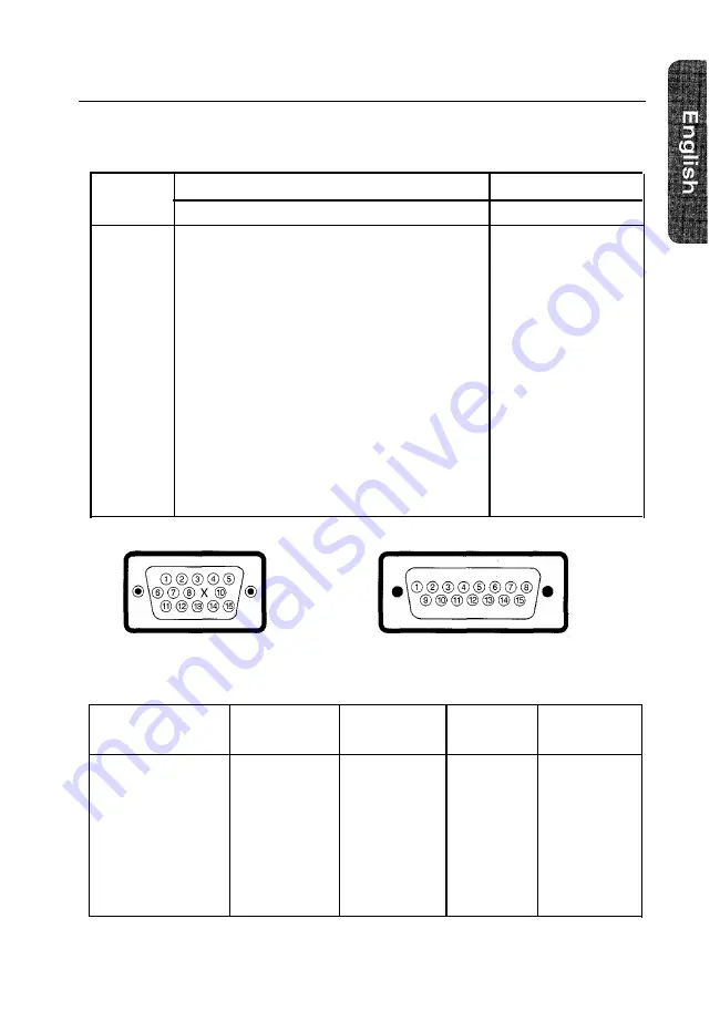
Pin Assignments

Sync Type

15 Pin Side of the Signal Cable (Figure 1)

Pin No.

Separate

Composite

1

Red

Red

2

Green

Green

3

Blue

Blue

4

GND

GND

5

DDC Return

DDC Return

6

GND-R

GND-R

7

GND-G

GND-G

8

GND-B

GND-B

9

Reserved

Reserved

10

GND-Sync/Self-Raster

GND-Sync/Self-Raster

11

GND

GND

12

DDC Data

DDC Data

13

H-Sync

H/V-Sync

14

V-Sync

Not Used

15

DDC Clock

DDC Clock

Figure 1 : Male Type

Cable Adapter (Figure 2

Apple MAC II

GND-R
Red

H/V Sync

Sense 0
Green
GND-G

Sense 1

Reserved

Blue
Sense 2
GND

V-Sync
GND-B

GND

H-Sync

Figure 2 : Male Type

Display Modes Timing Chart

Display Mode

Horizontal

Vertical

Pixel

Sync Polarity

Frequency (kHz) Frequency (Hz) Clock (MHz)

(H/V)

IBM, VGA2, 720 x 400

31.469

70.087

28.322

– / +

IBM, VGA3, 640 x 480

31.469

59.940

25.175

– / –

VESA, 640 x 480

37.500

75.000

31.500

– / –

VESA, 800 x 600

46.875

75.000

49.500

+ / +

VESA, 800 x 600

53.674

85.061

56.250

+ / +

VESA, 1024 x 768

60.023

75.029

78.750

+ / +

VESA, 1024 x 768

68.677

84.997

94.500

+ / +

13

Summary of Contents for SyncMaster 700S

Page 1: ...Samsung SyncMaster 700s Color Monitor Owner s Instructions ...

Page 2: ...sulated dangerous voltage within the product s enclosure that may be of sufficient magnitude to constitute a risk of electric shock The exclamation point within an equilateral triangle is intended to alert the user to the presence of important operating and servicing instructions in the literature accompanying the appliance Unpacking your Monitor Please make sure the following items are included w...

Page 3: ...rview 6 Direct Access Features 6 Contrast 6 Brightness 6 Control Function Features 7 Position H V User or Preset Model 7 Size H V 8 Geometric Distortion G D 8 Color Temperature 9 Recall 9 Degauss 9 PowerSaver 10 Troubleshooting 11 Appendix 12 Specifications 12 Pin Assignments 13 Display Modes Timing Chart 13 FCC Information 14 IC Compliance Notice 16 VCCI Information 16 MPR II Compliance 16 Europe...

Page 4: ...m of the cabinet If you put the moni tor in a bookcase or some other enclosed space be sure to pro vide adequate ventilation 7 Put your monitor in a location with low humidity and a minimum of dust Avoid places like damp basements or dusty hallways 8 Do not expose the monitor to rain or use it near water in kitchens next to swimming pools etc If the monitor accidentally gets wet unplug it and cont...

Page 5: ... of the display image 1 2 3 4 5 Brightness Use this rotary control to adjust the overall bright ness of the display image Contrast Use this rotary control to adjust the contrast level of the display image Power indicator This light glows green during normal operation and glows amber when you are making adjustments Power button Use this button to turn the monitor on and off 3 ...

Page 6: ...3 Chapter One Overview of Your Monitor Rear Panel 1 Power port Connect the power cable here 2 Signal port Connect your signal cable here 4 ...

Page 7: ...ompatible com puter skip to step 5 Follow the instructions included with your adapter to set the pins on your adapter if necessary 5 6 7 8 Connect the signal cable with the adapter if necessary to the video port on the back of your computer This port might be directly attached to your computer or it might be part of a video board video card or graphics card Connect the power cord for your monitor ...

Page 8: ...meric values as they change Direct Access Features The features described on this page can be accessed quickly at the touch of one button Contrast This feature will adjust the monitor s contrast Rotate the rotary control to the right to increase the contrast between dark colors and light colors or move it to the left to decrease the contrast Brightness This feature will adjust the overall brightne...

Page 9: ...ill automatically save your changes when the OSD remains inactive for approximately 8 seconds Position H V User or Preset Mode First Function Position H V Follow these instructions to change the position of the monitor s entire display 1 Push this button once to adjust the horizontal and vertical position centering of the display 2 Use the 4 and b buttons to change the horizontal position of the e...

Page 10: ...y are bowed in or bowed out adjust the trapezoid setting to equalize the length of the top and bottom edges 1 Push this button once to access the pincushion and trapezoid functions 2 Use the 4 and b buttons to change the pincushion setting use the V and A buttons to change the trapezoid setting Second function Parallelogram Tilt Adjust the parallelogram setting when the display is lean ing left or...

Page 11: ... the current video signal timing have been recalled The OSD shows the progress of the recall function Note This operation resets all of the data in the user memory area for the current timing signal Degauss The Degauss feature will remove any color impurity caused by magnetic fields Do not use the Degauss feature more than once within a 30 minute period Push the button once to activate the degauss...

Page 12: ...rtical Sync Active Active Inactive Inactive Video Active Blanked Blanked Blanked Power Green Amber Amber Green Amber Indicator Blinking Blinking Power 1OOW max Consumption 90W nominal 55W nominal Less than 15W Less than 8W NOTE This monitor automatically returns to normal opera tion when horizontal and vertical sync return This occurs when you move the computer s mouse or press a key on the keyboa...

Page 13: ...or and the computer are plugged in and turned on Check Signal Cable appears l Check the signal cable connection between the com puter and the monitor The image is too light or too dark l Adjust the Brightness or Contrast settings The image is too large or too small l Adjust the Size settings The colors are distorted with dark or shadowed areas l Activate the Degauss feature l Adjust the Color Temp...

Page 14: ...ontal 306 3 mm 12 05 0 12 Vertical 230 3 mm 9 06 0 12 Active display size is dependent upon signal timing Analog 0 714 Vpp positive at 75 Ω Separate sync TTL level positive or negative Composite sync TTL level positive or negative 110MHz AC 100 240 Volt 10 60 Hz 50 Hz 3 Hz 100 Watt maximum Unit 424 x 446 x 425 mm 19 Kg 16 7 x 17 6 x16 7 in W x D x H 41 9 Ibs Carton 545 x 554 x 538 mm 22 kg 21 5 x ...

Page 15: ...DC Clock Figure 1 Male Type Cable Adapter Figure 2 Apple MAC II GND R Red H V Sync Sense 0 Green GND G Sense 1 Reserved Blue Sense 2 GND V Sync GND B GND H Sync Figure 2 Male Type Display Modes Timing Chart Display Mode Horizontal Vertical Pixel Sync Polarity Frequency kHz Frequency Hz Clock MHz H V IBM VGA2 720 x 400 31 469 70 087 28 322 IBM VGA3 640 x 480 31 469 59 940 25 175 VESA 640 x 480 37 5...

Page 16: ...n accordance with the instructions may cause harmful interference to radio communications However there is no guarantee that interference will not occur in a particular installation If this equipment does cause harmful interference to radio or television receptions which can be determined by turn ing the equipment off and on the user is encouraged to try to correct the interference by one or more ...

Page 17: ...t use shielded signal interface cables to maintain FCC compliance for the product Provided with this monitor is a detachable power supply cord with IEC320 style terminations It may be suitable for connection to any UL Listed personal computer with simi lar configuration Before making the connection make sure the voltage rating of the computer convenience outlet is the same as the monitor and that ...

Page 18: ...ause of radio interference Read the instruc tions for correct handling MPR II Compliance The SyncMaster 700s monitor complies with SWEDAC MPR II recommendations for reduced electric and mag netic fields European Notice Manufacturer Samsung Electronics Co Ltd Model Number SyncMaster 700s Products with the CE Marking comply with both the EMC Directive 89 336 EEC 92 31 EEC 93 68 EEC and the Low Volta...

Page 19: ...distortion 8 I IC compliance notice 16 Installation 5 M Macintosh 5 Manual i i MPR II compliance 16 P Paralleolgram 8 Pin assignments 13 Pincushion 8 Position 7 Power button 3 Power cable i i Power indicator 3 Power port 4 Powersaver 10 Preset mode 7 R Rear panel 4 Recall 9 S Safety Signal cable Signal port Size Specifications Stand T Tilt Trapzoid Troubleshooting U User mode V VCCI information W ...

Page 20: ......

Page 21: ......

Page 22: ... Fax 507 269 5568 CODE NO BH68 60709A Rev 0 2 ESPAÑA Samsung Electrónics Comercial Ibérica S A Ciencies 55 65 Polígono Pedrosa 08908 Hospitalet de Llobregat Barcelona Tel 93 261 67 00 Fax 93 261 67 50 UK Samsung Electronics UK Ltd Samsung House 225 Hook Rise South Surbiton Surrey KT6 7LD Tel 0181 391 0168 Fax 0181 397 9949 European Service Center National Service Stafford Park 12 Telford Shropshir...

Reviews: