background image

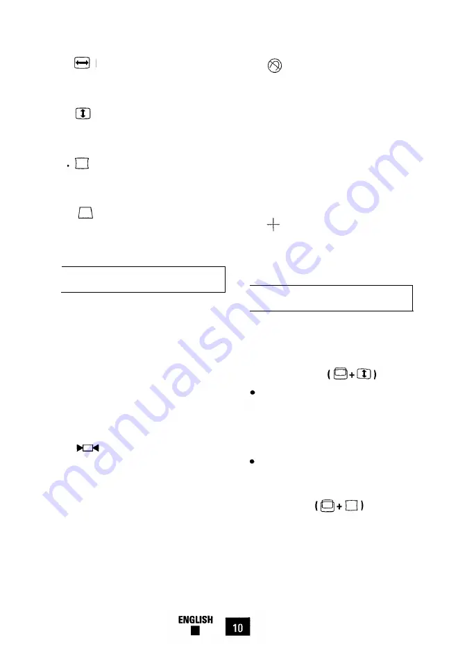
7.     Horizontal Size

Use this button to adjust the horizontal
size ( width ) of the display area.

8.      Vertical Size

Use this button to adjust the vertical size
( height ) of the display area.

9.     Side Pincushion

Use this button to correct a bowing in or
out of the display area.

10.    Trapezoid

Use this button to correct a trapezoid

( shape ) of the display area.

Display Adjustment Buttons

Use these buttons to adjust the display

area while a control function is imple-
mented ( the indicator’s color is orange ).

However, you cannot adjust the display

area when a control function is disabled
( the indicator’s color is green ).

Note: 

3 to 4 seconds after completing

adjustments your settings automatically
save, and the indicator returns to its nor-
mal status “green.”

11.  Recall

Use this button to recall factory modes
settings. Press the button for 2 to 3 sec-
onds until the indicator LED color changes

from orange to green.

Caution: 

This operation resets all of the

data in the user memory area for the cur-
rent signal timing.

12.  Degauss

Magnetic fields can build up on the CRT
and cause color impurity. Use the degauss
button to demagnetize the CRT. Push the
button once to activate the degaussing cir-

cuit. The degaussing circuit automatically
turns itself off after a few seconds.

13. — Decrease

Use this button to decrease the value of

the selected function. See Adjustment

Examples, pages 12 and 13.

14.                     

Increase

Use this button to increase the value of
the selected function. See Adjustment
Examples, pages 12 and 13.

Technical Control Functions

Your monitor has the following technical
control functions for the correction of geo-

metric distortion.

15. Parallelogram 

Use and hold both the vertical position
button and vertical size button simul-

taneously for 4 to 5 seconds, or until
the indicator’s color changes from

orange to green.

Use the Plus ( + ) or Minus (-) button

to control parallelogram of the display
area.

16. Pinbalance

l

Press and hold both the vertical posi-

tion button and side pincushion button

simultaneously for 4 to 5 seconds, or
until the indicator’s color is changes

from orange to green.

Summary of Contents for SyncMaster 15GLe

Page 1: ...SyncMaster 15GLe 38 Cm 15 Diagonal Basic CMA5377L User s Manual n n n n n n n n n n n n n n n n n n n n n n n n n n n n n n n n n n n n n n n n n n n n COLOR DISPLAY UNIT ...

Page 2: ... with SWEDAC MPR II recommendations for reduced electric and magnetic fields Table of Contents Introduction About This Manual Features of Your Monitor Safety Tips Installation Connection to Your Computer IBM or PC Compatible Macintosh Controls and Adjustments Controls and Their Locations Basic Controls and LED Indicator Functions Microprocessor Controls and Functions Control Function Buttons Displ...

Page 3: ...ization for Standards which con ferred its prestigious ISO certification to Samsung for product quality For you the end user Samsung s quality means reliability You are assured that your SyncMaster monitor will deliver crisp high resolution images and trouble free performance day after day year after year Samsung stands for technology Every SyncMaster monitor meets stringent inter national ergonom...

Page 4: ...timing settings that have been preset at the factory Please take the time to read through this manual so that you can obtain the maxi mum performance and use from your mon itor After reading the manual store it in a safe place for future reference Warranty Registration Card Optional You will find a Warranty Registration Card included with your monitor See contents of your package Please fill out t...

Page 5: ...efinable display settings Also includes 11 fac tory preset display settings Safe workplace design SyncMaster 15GLe complies with SWEDAC MPR II recommendations for reduced electric and magnetic fields Monitor provides compatibility with a wide variety of video standards includ ing IBM VGA XGA Super VGA Apple Macintosh II and 1024 x 768 non inter laced Power supply operates on AC 100 240 Volt and 60...

Page 6: ... other enclosed space be sure to provide adequate ventilation 7 8 9 10 11 12 13 Put your monitor in a location with low humidity and a minimum of dust Avoid places like damp basements or dusty hallways Do not expose the monitor to rain or use it near water in kitchens next to swimming pools etc If the monitor accidentally gets wet unplug it and contact an authorized dealer immedi ately You can cle...

Page 7: ...or complements a wide range of IBM and PC compatible systems To attach the monitor to this type of sys tem follow these instructions Connect the other end of the signal cable to the video connector on your computer s video controller Tighten the screws of the signal cable to ensure proper connection Note Your computer system has one of two configurations 1 Turn off the power to the monitor and com...

Page 8: ... adapter to output extended resolution modes To turn on monitor Use the power switch on the monitor s front panel The LED indicator should glow green see Basic Controls and LED Indicator Functions page 9 Connection to Your Computer Macintosh Computer I This monitor requires a cable adapter for use with a Macintosh computer The MacMaster Cable Adapter sup ports all monitors and all Macintosh Centri...

Page 9: ... monitor sig nal cable onto the cable adapter to ensure proper connection Connect one end of the power cord to the monitor and other end to the power outlet Power on your monitor and Macintosh computer If you see any message on your monitor screen installation is done If you do not see any messages check each of your connections and DIP switch settings and reboot your system 9 If you need more inf...

Page 10: ... Panel Press the center of the control panel to gain access to these controls 16 Pinbalance 15 Parallelogram 17 Vertical Linearity 6 V Position 8 V Size 10 Trapezoid 12 Degauss 14 Increase 3 Contrast Control 5 H Position 7 H Size 11 Recall 13 Decrease 4 Brightness Control 9 Side Pincushion ...

Page 11: ...isplay stet The monitor has factory mode display settings for each of the signals listed in the standard Timing Signal Chart see Appendix pages 18 and 19 As a result when the monitor senses one of the stan dard timing signals it automatically adjusts to an optimum size and position However you may wish to adjust the mon itor to your own preferred settings rather than those preset at the factory Th...

Page 12: ... the data in the user memory area for the cur rent signal timing 12 Degauss Magnetic fields can build up on the CRT and cause color impurity Use the degauss button to demagnetize the CRT Push the button once to activate the degaussing cir cuit The degaussing circuit automatically turns itself off after a few seconds 13 Decrease Use this button to decrease the value of the selected function See Adj...

Page 13: ...Sync Video Inactive Inactive Blanked Power Indicator Power Consumption Power saving function mode EPA NUTEK Stand by mode Suspend mode Position A1 Normal operation Active Inactive Active Active Active Blanked Green Orange Active Inactive Blanked Orange Green Blinking 85W max 68W max Less than 67 5W nominal 40 5W nominal 15W Orange Blinking Less than 5W Note The monitor automatically returns to the...

Page 14: ...sh the Vertical Size button Push the Minus button to decrease the Vertical Size Picture is too small vertically Push the Vertical Size button Push the Plus button to increase the Vertical Size Picture shifted to the right Push the Horizontal Position button Push the Minus button to move image to the left Picture shifted to the left Push the Horizontal Position button Push the Plus button to move i...

Page 15: ...e the bottom size Push the Trapezoid button Push the Plus button to Increase the bottom size Push the Vertical Position and Vertical Size buttons simultaneously Push the Minus button to adjust to the left Push the Vertical Position and Vertical Size buttons simultaneously Push the Plus button to adjust to the right Push the Vertical Position and Side Pincushion buttons simultaneously Push the Plus...

Page 16: ...ars l Check to see that signal l Rear Your computer cable pin assignment is correct Documentation This manual page 17 l Check to see that signal l Rear Your computer cable pin assignment is correct Documentation This manual page 17 Image is too dark or too bright LED indicator color is blinking on off orange Image is too large or too small Image is only raster l Check to see if the frequency l You...

Page 17: ...onsumption Dimensions Weight Approximately Environmental Considerations l Unlimited colors l Horizontal 1024 dots l Vertical 768 lines l Horizontal 267 mm 3 mm 10 5 0 19 l Vertical 200 mm 3 mm 7 87 0 19 Active display size is changed by timing signal l Horizontal 280 mm 11 02 l Vertical 210 mm 8 27 l Video Signal Analog 0 714 Vpp Positive at 75 Terminated l Separate Sync TTL Level Positive or Nega...

Page 18: ...r or an experienced radio TV technician for help User Information Changes or modifications not expressly approved by the party responsible for com pliance could void the user s authority to operate the equipment If necessary consult your dealer or an experienced radio television technician for additional suggestions You may find the booklet called How to Identify and Resolve Radio TV Interference ...

Page 19: ...n No 1 2 3 4 5 6 7 8 9 10 11 12 13 14 15 Both Ends of the Signal Cable Cable Adapter Figure 1 Figure 2 Separate Composite Apple Macintosh Red Red Gnd R Green Green Red Blue Blue H V Sync GND GND Sense 0 DDC Return DDC Return Green GND R GND R Gnd G GND G GND G Sense 1 GND B GND B Reserved Reserved Reserved Blue GND Sync Self Raster GND Sync Self Raster Sense 2 GND GND Gnd DDC Data DDC Data V Sync ...

Page 20: ...5 422 25 422 25 422 22 806 20 000 E µsec 0 636 0 636 0 636 0 178 1 000 fv Hz 70 086 70 087 59 940 86 958 60 317 O msec 14 268 14 268 16 683 11 500 16 579 P msec Q msec R msec S msec Clock Freq MHz Polarity H Sync V Sync Remark 0 064 0 064 0 064 1 907 1 080 1 048 11 122 12 711 15 253 1 176 0 413 0 318 25 175 28 322 25 175 Positive Negative Negative Negative Positive Negative 0 113 0 106 0 563 0 607...

Page 21: ... 0 762 0 508 0 323 0 369 fv Hz 72 809 75 000 75 000 60 004 O msec 13 735 13 333 13 333 16 666 P msec 0 079 0 080 0 064 0 124 Q msec 0 739 0 427 0 448 0 600 R msec 12 678 12 800 12 800 15 880 S msec 0 237 0 027 0 021 0 062 Clock Freq MHz 31 500 31 500 49 500 65 000 Polarity H Sync Negative Negative Positive Negative V Sync Negative Negative Positive Negative Remark 2 116 1 117 3 175 3 910 21 164 14...

Page 22: ...orrect handling PLUG AND PLAY Samsung s adoption of the new Microsoft Windows 95 Plug and play solution elimi nates complicated and time consuming setup It allows you to install your monitor in a Plug and Play compatible system without the usual hassels and confusion Your PC system can easily identify and configure itself for use with your monitor This monitor automatically tells the PC system its...

Page 23: ......

Page 24: ...B H 6 8 6 0 0 4 5 A R e v 0 0 EPA POLLUTION PREVENTER Printed on the recyclable paper ...

Reviews: