background image


36


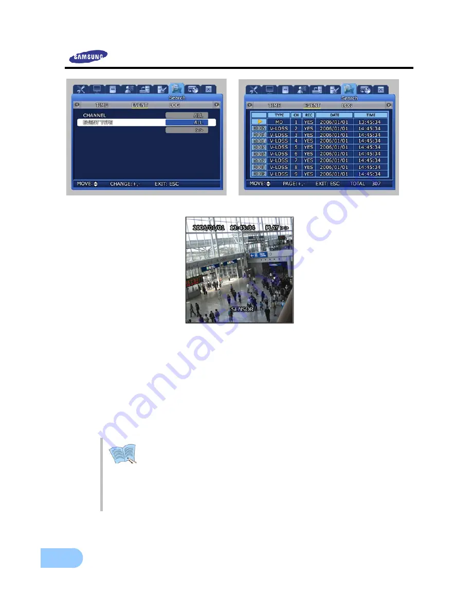
Channel [CH1

  16/ALL] : Select a channel for event search. 


Event type : Event type can be filtered for all events or [SENSOR/V-LOSS/MD/TEXT]

. 

9


SENSOR : Sensor events   

9


V-LOSS : Video loss events 

9


MD : Motion detection events   

9


TEXT : Text input events 


 If number of video recording items exceeds the number that can be displayed 

on one screen, use the (+)/(-) buttons on the remote controller or the main 
body to move between pages. 
 
If a video recording item is selected and ENTER button is pressed, the 
corresponding video recording will be played. 
 
To return to the EVENT LIST, press the ECS button again. 


Summary of Contents for SVR-1650

Page 1: ...ecorder SVR 1650 1640 User s Manual Thank you for purchasing a Samsung Digital Video Recorder Before attempting to connect or operate this product please read these instructions carefully and save thi...

Page 2: ......

Page 3: ...party to take any responsibility on its behalf Product warranty does not cover cases of accidents negligence alteration misuse or abuse In addition no warranty is offered for any attachments or parts...

Page 4: ...16 Chapter 3 Installation method 20 3 1 Overall connection 20 3 1 1 Front connection method 20 3 1 2 Back connection method 20 3 2 Detailed connection 21 3 2 1 Rack mount 21 3 2 2 Video Audio connect...

Page 5: ...Quick setup 43 4 12 PIP 44 4 13 System information 45 4 14 SPOT 45 Chapter 5 Setup method 46 5 1 Menu organization 46 5 2 Initial value setup 48 5 3 Operation description 54 5 4 FUNCTION menu 55 5 4...

Page 6: ...rch 80 5 12 Copy 81 5 13 Exit 82 Chapter 6 Network viewer program 83 6 1 Introduction 83 6 1 1 System requirements 83 6 1 2 Program installation 84 6 2 DVR MANAGER Function 85 6 3 VIEWER screen functi...

Page 7: ...onnected to reduce electric shock risk During operation 9 Do not open the product cover except qualified personnel or system installer Opening the product cover may cause an electric shock 9 Do not pl...

Page 8: ...with at least 15cm of space between the cooling ventilation opening and a wall 9 To prevent falling install the product in a flat area Dropping the product may cause an injury or a malfunction 9 Avoid...

Page 9: ...f This Product Waste Electrical Electronic Equipment Applicable in the European Union and other European countries with separate collection systems This marking shown on the product or its literature...

Page 10: ...e This product is a digital video recorder that digitizes 16 channels of video input and stores it in the built in hard disk drive Product functions can be setup conveniently using the mouse and butto...

Page 11: ...setup of video recording resolution and motion detection for each channel Video recording setup of up to 480 NTSC SVR 1650 120 NTSC SVR 1640 or 400 PAL SVR 1650 100 PAL SVR 1640 frames per second pos...

Page 12: ...from a remote location is possible entire or 4 DIVISION screen selection is possible PC playback storage search function and DVR control function using the network viewer is possible Search and playb...

Page 13: ...he following accessories Please verify whether all accessories are included at the time of purchase If any accessory is missing inquire at the point of purchase 2 3 Name and Function of Each Part 2 3...

Page 14: ...in progress HDD display LED Indicates whether hard disk drive is in operation NETWORK display LED Indicates whether network is in connection ALARM display LED Indicates whether event is in detection...

Page 15: ...mory Stick at the preset time 18 SEARCH Select data search mode 19 MULTI Convert to a divided screen 20 FUNCTION Display the LIVE screen menu for FUNCTION 21 PTZ Select PTZ mode 22 ENTER Store or exec...

Page 16: ...controller speed dome camera SRX 100B connector 13 TERMINATION Switch for RS 485 termination resistor setup 14 USB Terminal to connect external equipment DVD RW CD RW etc 15 VGA OUTPUT Output port to...

Page 17: ...ay 12 STOP Cancel playback mode 13 STEP Playback 1 frame 14 PLAY PAUSE Playback and pause 15 FAST High speed playback 16 DIR Change playback direction forward direction or reverse direction 17 Move cu...

Page 18: ...l BNC spot composite Front 1 terminal RCA composite Loop BNC 16 CH output VGA output PC monitor RGB output PIP screen PIP screen size 240 160 Fixed on left top side PIP screen organization Small live...

Page 19: ...Specification Remote controller Infrared LED Max 5m Mouse USB Menu setup and DVR setup handling possible Dedicated controller SCC 3100 RS 485 Hard disk drive Items Specification Max no of mounts 4 Ba...

Page 20: ...SUPER HIGH MID LOW Pre Alarm Setup possible within maximum 5 seconds Post Alarm Setup possible within maximum 5 minuets Countries using NTSC USA Canada Japan Korea Taiwan Mexico etc Countries using P...

Page 21: ...Event item Alarm motion detection video loss Playback speed and direction Forward direction reverse direction High speed search Fast forward 2 4 8 Max reverse 2 4 8 MAX Pause and frame playback Playb...

Page 22: ...and external devices is as follows Mouse Memory stick Speaker TV Monitor Use only DVD RW CD RW Media MONITOR A2 CH16 CH15 CH14 CH13 CH12 CH11 CH10 CH9 CH8 CH7 CH6 CH5 CH4 CH3 CH2 CH1 MONITOR A1 MONIT...

Page 23: ...1 3 3 2 Detailed connection 3 2 1 Rack mount To mount the product the enclosed rack must be mounted first Mount sequence is as follows The enclosed rack mount is mounted on the product The product is...

Page 24: ...ed image quality may be adversely affected Input video system type NTSC PAL is recognized automatically when the product power button is pushed However if a CCTV using a different system type is conne...

Page 25: ...ion Appropriate devices must be connected to store or output voice information Voice input Connect a RCA voice input terminal like a line level input to the AUDIO IN terminal in the back of the produc...

Page 26: ...2 13 S8 S9 S10 S11 S12 S13 SENSOR 8 SENSOR 9 SENSOR 10 SENSOR 11 SENSOR 12 SENSOR 13 21 22 23 24 25 GND GND GND GND GND Ground Ground Ground Ground Ground MONITOR A2 CH16 CH15 CH14 CH13 CH12 CH11 CH10...

Page 27: ...Description No Description 1 NO1 Normal Open 14 D_IO 0 Digital I O 2 CM1 Common 15 D_IO 1 Digital I O 3 NC1 Normal Close 16 D_IO 2 Digital I O 4 NO2 Normal Open 17 D_IO 3 Digital I O 5 CM2 Common 18...

Page 28: ...ot connected 5 GND Ground GND Ground 6 N C Not connected N C Not connected 7 Tx Data Send Data PORT A Controller SCC 3100 Control 8 Tx Data Send Data 9 Rx Data Receive Data 10 Rx Data Receive Data 11...

Page 29: ...terminal RS 422 485 connection can be selected from the SW1 switch To connect RS 485 SW1 switch 1 2 are turned ON To connect RS 422 SW1 switch 1 2 are turned OFF DVR PORT A Controller Terminal PORT 1...

Page 30: ...28 PORT B SPD 2200 terminal Speed dome terminal DVR PORT B D 9 or 16 D 10 or 15 GND 13 If GND is connected a much sharper image quality can be seen TERM2 switch 1 2 must be set to ON...

Page 31: ...be seen TERM2 switch 1 2 must be set to ON SPD 2300 3000 3300 terminal DVR PORT B Speed dome terminal RS 485 RS 422 RXD 9 or 16 16 RXD 10 or 15 15 TXD 9 TXD 10 GND 13 TX Terminal for RS 232 communicat...

Page 32: ...C Not connected 6 N C Not connected 2 RxD Data receive 7 N C Not connected 3 TxD Data send 8 N C Not connected 4 N C Not connected 9 N C Not connected 5 GND Ground No Description No Description 1 Red...

Page 33: ...upply After connecting the product with other equipment including the power supply cable turn ON the power by pressing the stand by switch button in front of the product When product is turned ON vide...

Page 34: ...pressed icons for FUNCTION LIVE will be activated FUNCTION icon can be used to setup SPOT PTZ and PIP In the FUNCTION PLAY screen the following play screen will be displayed 4 3 2 Single channel scre...

Page 35: ...n If MULTI button is pressed once again a 4 DIVISION screen is displayed Each time MULTI button is pressed a divided screen is displayed following the order for divided screen types setup in Screen Se...

Page 36: ...Setup RECORD RECORD MODE in the menu scheduled video recording is carried out automatically according to the reservation setup REC button is not operational during scheduled video recording Video rec...

Page 37: ...on is pressed images stored in the basic built in HDD can be setup by time periods and played As shown below date and time video recording was carried out is displayed If the desired date and time is...

Page 38: ...Motion detection events 9 TEXT Text input events If number of video recording items exceeds the number that can be displayed on one screen use the buttons on the remote controller or the main body to...

Page 39: ...ton is as follows 9 STEP Frame play Press the STEP button from the video recorded screen to play it in a frame Each time the button is pressed a small frame is played 9 PLAY PAUSE If PAUSE button is p...

Page 40: ...version If there is a video recording press the PLAY PAUSE button from the LIVE screen to get to the PLAY screen Press the STOP button from the PLAY screen to return to the LIVE screen Conversion from...

Page 41: ...y stick The device connected to the product will be automatically recognized and displayed on the menu After selecting a storage medium select the channel for which COPY will be carried out and the i...

Page 42: ...ed USB memory stick SanDisk Transcend 512MB recommended 3 If DVD RW CD RW media are not detected please install a UDF reader RW CD detection program UDF reader is a freeware that can be easily searche...

Page 43: ...on the front of DVR is pressed after the A button is selected focus is adjusted automatically 9 To exit the PTZ mode press the mouse right button or the ESC key PTZ mode can only be used in LIVE scre...

Page 44: ...reset values setup in advance 4 10 4 Using OSD for the Speed Dome Camera 9 After pressing the PTZ button from the single screen if either the ENTER key in the front of the DVR or the mouse button is p...

Page 45: ...roduct 9 RECORDE MODE Manual Event or Schedul Event setup item 9 EVENT CHECK Can be set to OFF ALWAYS or TIMEZONE 9 TIME SETUP Setup the system time 9 DATE FORMAT Setup the date display format 9 LANGU...

Page 46: ...om Live screen 1 Press the FUNCTION button and select the PIP icon 2 From the menu on the right side of the live screen select the desired channel 3 If the desired channel is selected with the mouse a...

Page 47: ...screen above video recording program information and version IP address MAC address voice information can be verified If mouse right button or ESC button is pressed the information screen is closed 4...

Page 48: ...ap pt te er r 5 5 S Se et tu up p m me et th ho od d 5 1 Menu organization Menu organization for DVR is as follows Quick Setup Screen Setup Record Setup Event Setup Communication System Setup Search...

Page 49: ...0 for details SAVE DO NOT SAVE NETWORK RS232C RS422 485 E MAIL SCREEN SEQUENCING DISPLAY COVERT SPOT RECORD PROGRAM EVENT MD RELAY TEXT SYSTEM HDD PASSWORD DATE SETUP PTZ TIME EVENT LOG COPY STATUS Sc...

Page 50: ...ME ORDER MULTI MODE VIDEO LOSS SKIP 3 sec CH1 16 CH1 CH16 4DIV A 4DIV E 9DIV A 9DIV B 16DIV 4DIV CH1 CH5 CH9 CH13 9DIV CH8 CH16 OFF DISPLAY DATE TIME HDD FREE SPACE RECORD STATUS TITLE REMOTE ID ON ON...

Page 51: ...S 10 S I 704 X 240 10 H 20 S 704 X 288 10 H 20 S J 704 X 240 10 H 15 S 704 X 288 10 H 15 S K 704 X 240 5 H 10 S 704 X 288 5 H 10 S L 704 X 240 5 H 10 H 704 X 288 5 H 10 H M 704 X 240 3 H 5 H 704 X 288...

Page 52: ...4 S I 704 X 240 3 M 5 H 704 X 288 3 M 3 H J 704 X 240 1 M 3 S 704 X 288 1 M 3 S K 704 X 240 1 H 3 S 704 X 288 1 H 3 S L 352 X 240 7 S 9 S 352 X 288 6 S 7 S M 352 X 240 5 H 10 S 352 X 288 4 H 5 S N 35...

Page 53: ...LOSS POWER OFF TEXT SYNC CHANNEL DEVICE CHECK PROTOCOL LINES CH1 NORMAL OFF 1 Communication Main menu Lower menu Initial value NETWORK TYPE DHCP IP ADDRESS SUBNET MASK GATEWAY DNS PORT SWR Ethernet O...

Page 54: ...WORD ADMIN PASSWORD SETUP POWER ON POWER OFF RECORD OFF PLAY BUZZER IF CHECKING FAILS 22222222 11111111 OFF OFF OFF OFF OFF OFF DATE SETUP TIME SETUP DATE FORMAT DAYLIGHT SAVING YY MM DD OFF PTZ CH NU...

Page 55: ...SVR 1650 1640 User Manual 53 5 Copy Main menu Lower menu Initial value COPY COPY STATUS 1 NONE GSA H10A 2 NONE 3 NONE 4 NONE NO DATA Exit Main menu Lower menu Initial value SAVE DO NOT SAVE...

Page 56: ...eft and to the right 9 Move the cursor up and down 9 Used to increase or decrease the value to be setup 9 Move the cursor and press the ENTER button to select the corresponding characters 9 Press the...

Page 57: ...version to the PLAY screen occurs For single screen mode setup in the PLAY screen PLAY functions SPOT MULTI D ZOOM and PIP can be setup If PLAY PAUSE button is pressed while in MULTI mode D ZOOM funct...

Page 58: ...9 SYSTEM INFORMATION 2 Displays VERSION IP ADDRESS MAC ADDRESS and AUDIO information SPOT If SPOT button is clicked the SPOT setup screen is displayed SPOT monitor can be used to view SINGLE or divide...

Page 59: ...n conversion function before using other function buttons If an Event is generated and EVENT SWITCH TO EVENT SCREEN is ON for Event Setup Automatic screen conversion function is halted for EVENT DISPL...

Page 60: ...he mouse is used 9 Main menu Main menu corresponding to each tab can be selected 9 Sub menu Lower menu that can be setup from the main menu can be selected 9 Setup items Setup items for the lower menu...

Page 61: ...SCREEN SEQUENCING DISPLAY COVERT SPOT related setup values may be modified 5 6 1 Screen Select a channel among the 16 available and setup the channel name brightness and contrast for that channel Each...

Page 62: ...matic conversion in the following order MULTI MODE 9 SEQ CH NUMBER Setup the screen display duration for each channel Setup range is Channel 1 16 ALL 9 DWELL TIME Setup the conversion display duration...

Page 63: ...VISION interval Setup display for a 9 DIVISION screen for 9 channels VIDEO LOSS SKIP ON OFF If setup as ON channels without image signals will be skipped automatically and only channels with image sig...

Page 64: ...played 9 RECORD STATUS ON OFF If setup as ON video recording status display NNNN is displayed in the upper right area of the screen during video recording 9 TITLE ON OFF If setup as ON titles for Chan...

Page 65: ...ck Covert is turned ON recorded images stored in HDD cannot be played back 5 6 5 SPOT Setup items for the SPOT monitor 9 TITLE DISPLAY Determines if title is to be displayed in the SPOT monitor 9 SPOT...

Page 66: ...rd mode setups manual and scheduled recording mode 9 M E Manual setup If REC button is pressed video recording is carried out 9 S E Video recording is carried out automatically according to the setup...

Page 67: ...ation Scheduled video recording mode can be used to setup the date and time when video recording will be carried out automatically 5 7 2 Record program PROGRAM can be used to adjust the FRAME RATE QUA...

Page 68: ...200 2 3 4 9 120 3 6 8 17 100 3 6 9 17 60 7 11 17 34 50 7 12 17 35 32 13 21 32 63 32 11 18 27 54 16 25 42 63 126 16 22 36 54 108 8 51 84 126 253 8 43 72 108 217 4 101 169 253 506 4 87 144 217 433 352...

Page 69: ...N Setup whether to convert the screen to the corresponding channel when an event occurs 9 EVENT DISPLAY MIN TIME Min retention time for the screen when an event occurs Amount of time to ignore an even...

Page 70: ...sed for motion detection 9 AREA SETUP Setup motion detection for each channel and specify the sensitivity and area with the mouse 9 AREA DISPLAY If motion is detected area related to motion can be dis...

Page 71: ...ted to the RELAY OUT terminal in the back of the product Blinking green box indicates the state before selection After selection it turns yellow 5 8 4 TEXT This setup allows material input with equipm...

Page 72: ...9 IP ADDRESS Input the IP address obtained from the internet service company of the user 9 SUBNET MASK Input the SUBNET MASK address obtained from the internet service company of the user 9 GATEWAY In...

Page 73: ...em to ON Changed IP address can be verified from FUNCTION STATUS SYSTEM INFORMATION 2 5 9 2 RS 232 Setup items needed to connect with the computer connected to the product through the serial port 9 BA...

Page 74: ...cond 9 DATA BIT Setup the data transmission bit 9 PARITY BIT Setup the error check method for data transmission 9 STOP BIT Setup bit to include when data transmission has been completed 5 9 4 E MAIL T...

Page 75: ...the mouse detailed items may be viewed 5 10 1 System 9 LANGUAGE Select a language for the menu screen 9 KEY BUZZER ON OFF Select whether to generate sound for key strokes when using the remote control...

Page 76: ...solution of each channel on network board This mode is supported in only SVR 1650 9 REMOTE SETUP ON OFF Used to determine remote setup mode 9 DVR ALIAS Used to identify network name 9 REMOTE ID Used t...

Page 77: ...at the built in fixed HDD If YES is clicked in the confirmation dialog window formatting is carried out 9 HDD Setup can be for HDD1 HDD4 or ALL Selection of HDD for format and information for the sele...

Page 78: ...F Select whether to input the password during setup 9 POWER ON ON OFF Select whether to input the password when product is turned ON 9 POWER OFF ON OFF Select whether to input the password when produc...

Page 79: ...reen 9 TIME SETUP Setup the time From the dialog box shown above use the mouse wheel or the buttons on the front of the product to modify the setup value Then select SET to make the assignment 9 DATE...

Page 80: ...l 9 CAMERA ID User can assign an ID between 0 255 for each camera 9 MODEL None SPD PELCO D PANASONIC SCC SRX Select the manufacturer for the connected camera Signal input from a camera is different fo...

Page 81: ...ovided If ENTER key located in the front of DVR is pressed or if lower level menu is selected with the mouse detailed items may be viewed 5 11 1 Time search If a desired date and time that is within t...

Page 82: ...luding loss video sensor and motion detection is possible Items selected during event search can be played back If ESC key is pressed during playback returns to the event search window 5 11 3 Log sear...

Page 83: ...key located in the front of DVR is pressed or if lower level menu is selected with the mouse detailed items may be viewed If USB and DVD RW CD RW storage is inserted a screen like the one shown below...

Page 84: ...applied when they are verified after the Save button is pressed 9 As shown in the screen below when setup has been modified and SAVE is pressed the setup functions are applied The setup functions can...

Page 85: ...Provides a wide variety of search methods for recorded content GUI screen automatic change depending on user PC resolution Provides separate Manager Backup program for the viewer Single and 4 9 16 div...

Page 86: ...cally in the PC Basic path to the execution file is as follows C Program File SAMSUNG TECHWIN DVR Viewer Program installation from the website Viewer program can be downloaded by connecting to http ww...

Page 87: ...password For Group item adding a new group from the local network modifying the name for an existing group and deleting a group is possible Password for initial execution is setup as admin To change...

Page 88: ...R main body must be entered accurately 9 If Append button is selected it is appended to the tree on the left side 9 If IP for a registered DVR is changed a list is later displayed if the Find button i...

Page 89: ...fter information receive is carried out the content is saved 9 List that has not been validated cannot be connected from the viewer 9 If the viewer is executed and the DVR is selected and then connect...

Page 90: ...tored from the client PC UI is changed to match user PC resolution The screen above shows a 1280 x 1024 image If no camera is connected the screen displays a black box 6 3 1 Name for each function Nam...

Page 91: ...m the and image display control front channel and back channel that cannot be seen in the image display section can be seen 9 Hides various buttons and status information and only displays images whos...

Page 92: ...the selected channel by 180 degrees Audio control and HDD display 9 Speaker volume is adjusted and if button is clicked speaker sound is muted 9 Microphone volume is adjusted and if button is clicked...

Page 93: ...y If the 4 buttons are clicked specific signals are sent to the DVR Search control 9 Assigns the play direction for the video recorded image 9 Moves to the front and back frame in the paused state 9 M...

Page 94: ...e screen shown below DVR Manager Program lock 9 To prevent others from using the program when the program user leaves the computer unattended the screen that was being used is minimized as an icon in...

Page 95: ...dicate image status Storage folder and Delete Recoded Data to be used in the program Live connect disconnect 9 Connect the DVR selected by the user from the DVR list so that it can be viewed in real t...

Page 96: ...and Get Info button is clicked time and channel information for the selected DVR is displayed 9 If desired time and channel for playback is selected and the button is pressed images recorded during t...

Page 97: ...DVR server is selected in DVR list on the left side if Get Info button is clicked the channel and the time period are displayed and then users can select a category for backup Log Functions used in t...

Page 98: ...e for DVR list will be activated in light green color 6 3 7 PTZ control section 9 Pan Tilt Zoom Focus for the speed dome camera is adjusted 9 When Pan Tilt Zoom Focus is adjusted speed can be specifie...

Page 99: ...he selected channel and a variety of other menu items may be used easily by using the popup menu 9 Selected channel is a function to control only the channel selected by the user and All channels is a...

Page 100: ...oller is not operating Check the batteries and replace them if needed Aim the remote controller propely at the product remote controller receiver section during operation If product and remote control...

Page 101: ...ter has entered the product If a liquid has been spilled on the product or if a foreign substance has entered the product If the product does not operate as described in this manual If the product has...

Page 102: ...0 100 SVR 1640 fps CIF 352 x 288 Recording Mode Manual Event Schedule Event HDD 250GB 1HDD Up to 4HDD Backup DVD RW 3 USB 2 Front USB Flash Memory Drive Serial Interface RS 232C RS 485 422 RJ 45 Senso...

Page 103: ...Dimensions...

Page 104: ...8137 8139 Fax 82 31 740 8145 TIANJIN SAMSUNG OPTO ELECTRONICS CO LTD 7 Pingchang Rd Nankai Dist Tianjin 300190 P R China Tel 86 22 2761 4724 33821 Fax 86 22 2761 6514 SAMSUNG OPTO ELECTRONICS UK LTD...

Reviews: