


Disassembly and Reassembly
Samsung Electronics
1-47
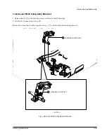
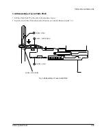
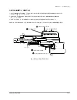
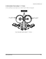
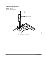
1-4-28 Assembly of Slide Main
1. Install the shaft of Loading ÒRÓ Gear AssÕy into the left of the Main Slide Hole and secure with the
Slit Washer
@
. (Refer to detail ÒAÓ)
2. Insert the Tension Control Lever
#
and the Idler Change Lever
$
into the Main Slide Hole.
(Refer to detail ÒBÓ)
3. After confirming the above items 1, 2 install the Main Slide and secure with tabs (a, b, c).
Note :
Be sure to assemble the Main Slide when the Loading L/R Gear AssÕy is in unloading position.
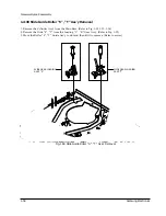
GEAR LOADING "R"ASS'Y
GEAR LOADING "L "ASS'Y
1
LEVER IDLER CHANGE
SLIDE MAIN
4
LEVER TENSION CONTROL
3
WASHER - SLIT
"a"
"d"
"b"
"C"
"B"
"A"
2
Fig. 1-48 Assembly of Slide Main
Summary of Contents for SV-510X
Page 4: ...Samsung Electronics 2 1 2 Reference Information 2 1 IC BLOCK 2 1 1 IC601 HD6473977 ...
Page 5: ...Reference Information 2 2 Samsung Electronics 2 1 2 IC301 SS11511M SS11501M ...
Page 6: ...Reference Information Samsung Electronics 2 3 2 1 3 IC302 LA7416 ...
Page 7: ...Reference Information 2 4 Samsung Electronics 2 1 4 IC303 SS23377M SS23378M ...
Page 8: ...Reference Information Samsung Electronics 2 5 2 1 5 IC501 LA72633 ...
Page 9: ...Reference Information 2 6 Samsung Electronics 2 1 6 IC801 KA8119 ...
Page 17: ...Disassembly and Reassembly 4 6 Samsung Electronics MEMO ...
Page 43: ...Block Diagrams 8 2 Samsung Electronics 8 1 Overall Block Diagram ...
Page 44: ...Block Diagrams Samsung Electronics 8 3 8 2 System Control ...
Page 45: ...Block Diagrams 8 4 Samsung Electronics 8 3 Video ...
Page 46: ...Block Diagrams Samsung Electronics 8 5 8 4 Hi Fi ...
Page 48: ...PCB Diagrams 9 2 Samsung Electronics 9 1 Main ...
Page 49: ...PCB Diagrams Samsung Electronics 9 3 ...
Page 50: ...PCB Diagrams 9 4 Samsung Electronics 9 3 SUB A2 NICAM SV 613F 610F Only 9 2 SUB A2 ...
Page 51: ...PCB Diagrams Samsung Electronics 9 5 9 5 Function Timer 9 4 SUB A2 NICAM ...
Page 52: ...Samsung Electronics 10 1 10 Wiring Diagram 230V or 100 240V 50 60Hz ...
Page 56: ...Schematic Diagrams 11 4 Samsung Electronics Hi Fi OPTION 11 2 System Control Servo ...
Page 57: ...Schematic Diagrams Samsung Electronics 11 5 11 3 Audio Video Hi Fi OPTION ...
Page 58: ...Schematic Diagrams 11 6 Samsung Electronics 11 4 Hi Fi ...
Page 59: ...Schematic Diagrams Samsung Electronics 11 7 11 5 IF L MONO Hi Fi OPTION FRANCE OPTION ...
Page 60: ...Schematic Diagrams 11 8 Samsung Electronics 11 6 I O ...
Page 61: ...Schematic Diagrams Samsung Electronics 11 9 11 7 SECAM SV 613F 610F Only ...
Page 62: ...Schematic Diagrams 11 10 Samsung Electronics 11 8 SUB A2 ...
Page 63: ...Schematic Diagrams Samsung Electronics 11 11 11 9 SUB A2 NICAM SV 613F 610F Only ...
Page 64: ...Schematic Diagrams 11 12 Samsung Electronics 11 10 SUB A2 NICAM ...
Page 65: ...Schematic Diagrams Samsung Electronics 11 13 11 11 VCS PDC ...
Page 66: ...Schematic Diagrams 11 14 Samsung Electronics 11 12 Function Timer ...
Page 67: ...Schematic Diagrams Samsung Electronics 11 15 11 13 Remote Control ...
Page 132: ...Disassembly and Reassembly 1 64 Samsung Electronics MEMO ...