


Reference Information
2-2
Samsung Electronics
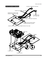
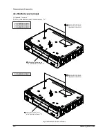
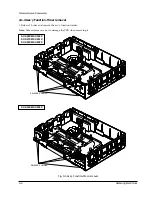
2-1-4 How to Connect X-5 chassis jig
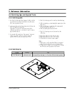
4. Insert wafers of drum motor, capstan motor and
loading motor on X-5 chassis jig into each of the
connectors of deck assÕy, and then secure with
three screws.
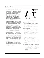
5. Solder the 3 leads of the jig cable to ÒCN605Ó
on the main PCB.
6. Apply power to the function PCB.
7. Insert a test tape into the housing assÕy.
8. Simultaneously touch the start and end sensor
LEDs on the PCB, so that the tape loads
automatically. After the tape is loaded, all of the
function buttons on the function PCB can be
used.
9. If the test tape is ejected while the jig is in use,
attempt to re-load the tape by simultaneously
touching the start and end sensor LEDs. If the tape
still does not load, reset the function PCB by
pressing SW715.
Note
: After completing repairs, SW715 on the function PCB in order to reset.
1. Unplug the power cord from AC outlet.
2. Remove the deck assÕy from main PCB (See Page
4-5 of service manual).
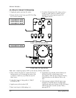
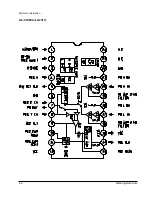
3. To emulate the function of the sensors, place a
jumper or solder land (two point) at service
option(W750) on the function-timer PCB.
(see diagram below).
Function-Timer (Component side)
Function-Timer (Component side)
SV-A20XK/SV-200X
SV-A21XK/SV-201X
SV-A30XK/SV-203X
SV-A40XK/SV-205X
Summary of Contents for SV-200X
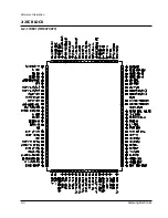
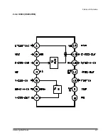
Page 7: ...Reference Information 2 4 Samsung Electronics 2 2 IC BLOCK 2 2 1 IC601 HD6473977 ...
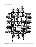
Page 8: ...Reference Information Samsung Electronics 2 5 2 2 2 IC301 SS11501M ...
Page 9: ...Reference Information 2 6 Samsung Electronics 2 2 3 IC302 LA7411 ...
Page 10: ...Reference Information Samsung Electronics 2 7 2 2 4 IC303 SS23478M ...
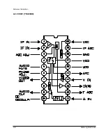
Page 11: ...Reference Information 2 8 Samsung Electronics 2 2 5 IC401 TDA9800 ...
Page 12: ...Reference Information Samsung Electronics 2 9 2 2 6 IC801 KA8119 ...
Page 13: ...Reference Information 2 10 Samsung Electronics MEMO ...
Page 23: ...Disassembly and Reassembly 4 8 Samsung Electronics MEMO ...
Page 31: ...Alignment and Adjustment 5 8 Samsung Electronics MEMO ...
Page 41: ...Exploded View and Parts List 6 10 Samsung Electronics MEMO ...
Page 59: ...Electrical Parts List 7 18 Samsung Electronics MEMO ...
Page 61: ...Block Diagrams 8 2 Samsung Electronics 8 1 Overall Block Diagram ...
Page 62: ...Block Diagrams Samsung Electronics 8 3 8 2 System Control ...
Page 63: ...Block Diagrams 8 4 Samsung Electronics 8 3 Video ...
Page 64: ...Samsung Electronics 10 1 10 Wiring Diagram ...
Page 67: ...Schematic Diagrams Samsung Electronics 11 3 11 1 S M P S POWER ...
Page 68: ...Schematic Diagrams 11 4 Samsung Electronics 11 2 System Control Servo ...
Page 70: ...Schematic Diagrams 11 6 Samsung Electronics 11 4 IF ...
Page 71: ...Schematic Diagrams Samsung Electronics 11 7 11 5 I O 1 Scart ...
Page 72: ...Schematic Diagrams 11 8 Samsung Electronics 11 6 I O 2 Scart ...
Page 73: ...Schematic Diagrams Samsung Electronics 11 9 11 7 VPS ...
Page 74: ...Schematic Diagrams 11 10 Samsung Electronics 11 8 PDC ...
Page 77: ...Schematic Diagrams Samsung Electronics 11 13 11 11 Remote Control ...