Alignment and Adjustments
Samsung Electronics
4-1
4. Alignment and Adjustments
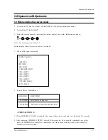
4-1 When entering the service mode:
1. Turn on the TV, and then select “STANDARD”on the picture adjustment mode.
2. Turn off the TV (STAND-BY).
3. Enter the service mode by pressing the remote control keys in the following sequence :
Note : If necessary, re-do steps 1~3.
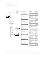
Initial display when the service mode is switched.
SERVICE / Sim-474A
DEFLECTION
480P OFFSET
1080i OFFSET
CONVERGENCE OFFSET
VIDEO ADJUST 1
VIDEO ADJUST 2
VIDEO ADJUST 3
VIDEO ADJUST 4
OPTION (E3h 98h 0ch)
RESET / 02-05-03
1. When a RF signal is received
MAIN MENU
MENU DISPLAY
CH UP/DOWN
Select item by moving cursor
VOL UP/DOWN
Decrease or increase the adjustment values
3. Service Mode Control Keys
<
PRECAUTIONS
>
1. When EEPROM IC (IC902) is replaced, first connect the power cord and wait for about 4~5 seconds.
2. After replacing EEPROM IC (IC902), enter the Service mode. Next, enter the standard data or the
previous EEPROM IC data before replacement. And then check and adjust any items related to
Geometric, Picture, Option.
Summary of Contents for ST55W3PCX/XAX
Page 10: ...Reference Information 2 4 Samsung Electronics 2 3 IC Line Up 2 3 1 Progressive ...
Page 11: ...Reference Information Samsung Electronics 2 5 ...
Page 12: ...Reference Information 2 6 Samsung Electronics 2 4 MICOM IIC BUS LINE UP ...
Page 14: ...MEMO 3 2 Samsung Electronics ...
Page 52: ...MEMO 4 38 Samsung Electronics ...
Page 56: ...MEMO 5 4 Samsung Electronics ...
Page 87: ...Schematic Diagrams 10 2 Samsung Electronics TP20 TP03 TP04 10 2 MAIN 2 TP03 TP04 TP20 ...
Page 88: ...Samsung Electronics Schematic Diagrams 10 3 10 3 MAIN 3 TP12 TP13 TP12 TP13 ...
Page 90: ...Samsung Electronics Schematic Diagrams 10 5 10 5 MICOM ...
Page 91: ...Schematic Diagrams 10 6 Samsung Electronics 10 6 CRT ...
Page 92: ...Samsung Electronics Schematic Diagrams 10 7 10 7 SUB 1 TP21 TP21 ...
Page 93: ...Schematic Diagrams 10 8 Samsung Electronics 10 8 SUB 2 TP24 TP23 TP22 TP22 TP23 TP24 ...
Page 94: ...Samsung Electronics Schematic Diagrams 10 9 10 9 CONVERGENCE SDC12 1 ...
Page 95: ...Schematic Diagrams 10 10 Samsung Electronics 10 10 CONVERGENCE SDC12 2 ...
Page 96: ...Samsung Electronics Schematic Diagrams 10 11 10 11 PRO SCAN 1 ...
Page 97: ...Schematic Diagrams 10 12 Samsung Electronics 10 12 PRO SCAN 2 ...
Page 98: ...Samsung Electronics Schematic Diagrams 10 13 10 13 PRO SCAN 3 ...
Page 99: ...Schematic Diagrams 10 14 Samsung Electronics 10 14 PRO SCAN 4 ...
Page 100: ...10 15 CG AMP Samsung Electronics Schematic Diagrams 10 15 ...
Page 101: ...Schematic Diagrams 10 16 Samsung Electronics 10 16 AV FRONT ...
Page 102: ...10 17 CONTROL Samsung Electronics Schematic Diagrams 10 17 ...
Page 103: ...Schematic Diagrams 10 18 Samsung Electronics 10 18 DY JACK SENSOR DY JACK SENSOR ...

