background image

10_


Connecting with Other Equipment

connecting with other equipment

You can use the SSC-5000 System Keyboard with a camera, DVR, and the other equipments.
This chapter describes how to connect each equipment.

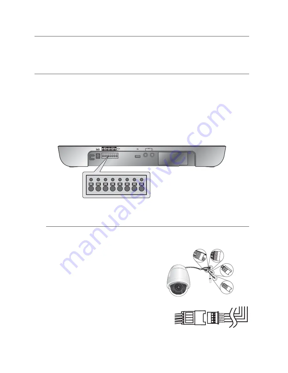
CONNECTING RS-485 DEVICE

- Connect RS-485 Device through the port in the back of SSC-5000.

- You are able to install and control the camera and DVR supporting RS-485 communication.

- Either Half Duplex or Full Duplex method is applicable for connection.

For the Half Duplex method, use TX +,-.

To connect RS-485, be careful not to be confused b and -.
Also, you shall check if the RS-485 device can support SSC-5000.

Please refer to “RS-485 Communication Setup” of “Menu Setup” for RS-485 communication setup. (see page 22)

Connecting the SAMSUNG Dome Camera

Connect with SSC-5000 by using the RS-485 port on the back of Dome Camera

In case of connecting with Half Duplex

- Connect the RX (+) of Dome Camera RS-485 port with the 

TX(+) of SSC-5000.

- Connect the RX (-) of Dome Camera RS-485 port with the 

TX(-) of SSC-5000.

In case of connecting with Full Duplex

- Connect the RX (+) of Dome Camera RS-485 port with the 

TX (+) of SSC-5000.

- Connect the RX(-) of Dome Camera RS-485 port with the 

TX (-) of SSC-5000.

- Connect the TX (+) of Dome Camera RS-485 port with the RX (+) 

of SSC-5000.

- Connect the TX (-) of Dome Camera RS-485 port with the RX (-) 

of SSC-5000.

M
M

M

W

W

TXD+
TXD-
RXD+
RXD-

Summary of Contents for SSC-5000

Page 1: ...tem Keyboard user manual SSC 5000 imagine the possibilities Thanks you for purchasing this Samsung product To receive a more complete service please register your product at www samsung com global register ...

Page 2: ...e electric shock or falling objects Do not install the unit in humid dusty or sooty locations Doing so may cause fire or electric shock If any unusual smells or smoke come from the unit stop using the product In such case immediately disconnect the power source and contact the service center Continued use in such a condition may cause fire or electric shock If this product fails to operate normally ...

Page 3: ...ce with the manufacturer s instructions Do not install near any heat sources such as radiators heat registers or other apparatus including amplifiers that produce heat Do not defeat the safety purpose of the polarized or grounding type plug A polarized plug has two blades with one wider than the other A grounding type plug has two blades and a third grounding prong The wide blade or the third prong...

Page 4: ...NT 10 10 Connecting RS 485 Device 12 Connecting to PC using USB port 12 Connecting Other System Keyboard 13 Basic System Diagram of SSC 5000 INSTRUCTIONS 14 14 Log in 15 Camera control 19 DVR control CONTENTS MENU SETUP 22 22 Main Menu 22 Keyboard Setup 22 RS 485 Communication Setup 23 Change Password 24 Check Password 24 Register New Operator 25 Camera Data Download 26 Camera Data Upload 27 Syste...

Page 5: ...t 2 or more System Keyboards together Maximum 32 keyboards can be connected simultaneously and the system can be controlled from different places Easy to operate There is an LCD showing the operating status of the System Keyboard Touch Screen that helps users to choose the menu easily and a Joystick Controllable products List Camera DVR SHR 4081 SHR 4160 SHR 504Xseries 508Xseries 516Xseries SHR 2X...

Page 6: ...nction of UP DOWN LEFT RIGHT keys is controlled in the menu screen of the connected controller Press the button of the top to execute ENTER motion Device select button MON CAM VMS DVR This key is to select Camera Monitor DVR or others DVR control button SEQUENCE MODE SEQUENCE Executes the SEQUENCE function of DVR MODE Executes the partition screen selection function of DVR Number 0 9 ENTER CLEAR b...

Page 7: ...eyboard Composite Video IN OUT This is an AV In Out port RS 485 Port1 2 For RS 485 communication it will be connected to the RS 485 terminals of other System Keyboards or controlling devices such as cameras and DVR You can specify different protocols for Port 1 and Port 2 M DC12V IN DC 12V power input terminal ...

Page 8: ...to this equipment can affect EMI so it is recommended to coil the CORE FERRITE for use CAUTIONS FOR INSTALLATION Be sure to turn the unit off before installing Avoid shock or vibration since they may cause unit malfunction Keep away from magnets radio or TV to avoid magnetic damage During or after installing the unit be sure to maintain the area around the unit clean Place the unit on a flat surfac...

Page 9: ...DJUSTING SYSTEM KEYBOARD ANGLE You may adjust the angle of the product as shown below FIXING POWER CORD Hang the power cord as shown in the following figure to prevent it from being deviated when you connect it with the main body ...

Page 10: ...l check if the RS 485 device can support SSC 5000 Please refer to RS 485 Communication Setup of Menu Setup for RS 485 communication setup see page 22 Connecting the SAMSUNG Dome Camera Connect with SSC 5000 by using the RS 485 port on the back of Dome Camera In case of connecting with Half Duplex Connect the RX of Dome Camera RS 485 port with the TX of SSC 5000 Connect the RX of Dome Camera RS 485...

Page 11: ...R 5042 DVR Connect to SSC 5000 through the RS 485 port on the rear of SHR 5040 SHR 5042DVR Connecting as Half Duplex Connect TX of RS 485 port of SHR 5040 SHR 5042 DVR to TX of SSC 5000 Connect TX of RS 485 port of SHR 5040 SHR 5042 DVR to TX of SSC 5000 Connecting SHR 204X Series DVR Connect to SSC 5000 through the RS 485 port on the rear of SHR 204X DVR Connecting as Half Duplex Connect TX of RS...

Page 12: ... simultaneously Refer to the ADDRESS SET part in RS 485 Communication Setup of Menu Setup for the setting of keyboard communication see page 22 Do not use together with the SSC 2000 SSC 1000 because it is different with the SSC 2000 SSC 1000 in communication method In case of connecting with Half Duplex Connect the TX of SSC 5000 port with the TX of another SSC 5000 Connect the TX of SSC 5000 port...

Page 13: ...es Daisy Chain Type Wiring Do not use together with the SSC 2000 SSC 1000 because it is different with the SSC 2000 SSC 1000 in communication method In case of using the keyboard connected SSC 931T Version 1 4 make sure the address of connected keyboards differ from each other 1 2 3 M Digital Video Recorder Digital Video Recorder Digital Video Recorder Digital Video Recorder Digital Video Recorder...

Page 14: ...stered password is entered a message of Invalid Password will appear on the screen and the log in process will return to the starting point automatically When you have logged in successfully the System Keyboard will enter the following camera control mode and display Normal Mode or Video Mode as in the right figure To change the display mode see Display Mode in System Information Setup see page 27 ...

Page 15: ... models released later than the SCC C6405 press the AUTO PAN button and enter the AUTO PAN number 1 4 then press the ENTER button to execute the AUTO PAN feature SCAN movement This function is to move between the preset positions that were set by the camera s scan mode Press SCAN button to execute the scan movement and you will see SCAN message during the scan movement Press the SCAN button again ...

Page 16: ...the preset number you want to save and press Enter PRESET DELETE This function is to delete the preset position Press Delete When a window appears as shown in the right figure enter the preset number you want to delete and press Enter The camera will move to the preset position you want to delete The system keyboard will show a message to confirm the deletion Press OK to delete or Cancel to cancel t...

Page 17: ... time until you complete the title you want Maximum 14 characters can be entered Press Back to delete the last word Press Space to leave a column vacant Press Clear to delete all the characters entered Press OK to save the title you entered Press the EXIT icon to cancel the title and return to the camera control mode W 1 2 3 4 5 M CAM 000 MON 001 001 000 TEXT text Number Symbol Back Space Clear OK...

Page 18: ...VR Press the DVR button of the keyboard on the connection information screen While the number is highlighted enter the number of the connected DVR by using the number keys and press the ENTER button CAMERA MENU Press the SETUP icon on left below to control the menu of the selected camera Using the direction key and the Enter key control the CAMERA MENU Press the EXIT icon to clear the camera menu ...

Page 19: ...button Varied window will appear depending on the DVR model If you press the DVR button in the Camera Control mode the DVR Input Box will be displayed in the screen as follows Then select DVR in the same manner as above Examples of DVR selecting 1 2 3 M 1 SHR 4081 SHR 4160 2 PC DVR 3 SHR 5040 5042 DVR SHR 4081 013 Select Channel MON 001 001 DVR SHR 5042 002 Select Channel MON 002 002 DVR SPR7416 0...

Page 20: ... None and then try resetting the PTZ device Selecting and operating the camera using the System Keyboard in DVR Control mode Press the CAM button on the keyboard in DVR Control mode The PTZ icon will appear at the left side of the screen as in the following image Using the number keys on the keypad enter the Channel number of the camera you wish to operate and press the ENTER button The camera can...

Page 21: ...cted by using the number keys 0 9 of the keyboard DVR MENU control Press the SETUP icon on the lower left to control the menu of the selected DVR Using the Direction key and the Enter key control the DVR MENU You can use the joystick as a direction or enter key by moving it or using the AF button Press the EXIT icon to finish controlling the DVR MENU 1 2 3 4 M DVR SPR7416 000 Enter DVR Setup DVR SP...

Page 22: ... setting of Duplex of keyboard is Half Duplex ADDRESS SET The address of the system keyboard can be set Press Address Set and the keyboard address input window will appear as shown in the right figure Enter the address by using the number keys and press the ENTER button Press the EXIT icon on lower left if you want to clear the window without entering the address ADDRESS 0 For only one unit ADDRESS...

Page 23: ...ARD SETUP screen CHANGE PASSWORD This function is to change the operator s password of the system keyboard At first enter the current Operator No and Password Correctly entered the screen will change into a window as follows M M 1 2 1 2 M 1 2 RS 485 Communication Setup Keyboard Setup Address Set 0 Protocol 1 Port 1 SAMSUNG Protocol 1 Port 2 SAMSUNG Baud Rate 9600 Duplex Half Duplex RS 485 Communica...

Page 24: ...set Off you can directly enter the MENU mode The system has been set On on shipment REGISTER NEW OPERATOR This function is to add a new user of the keyboard New Operator No Enter a new operator no Using the number keys 0 9 enter the operator no and press the ENTER button The number can be one between 1 and 99 New Password Enter a new password Using the number keys 0 9 enter the password and press ...

Page 25: ...data for the first time Download the setup data of the currently selected camera Press OK to start downloading Press Cancel or the EXIT icon to return to the Keyboard Setup screen If you want to download the data on the system An informing message will appear if there is already data stored in the system keyboard Press OK to start downloading Press Cancel or the EXIT icon to return to the Keyboard ...

Page 26: ...red will be uploaded to the selected camera Press OK to start uploading Press Cancel or EXIT icon to return to the Keyboard Setup screen UPLOAD progress screen When you press OK on the UPLOAD check screen UPLOAD progress screen will appear as in the right figure Complete message will appear when uploading is completed 1 2 Camera Data Upload No Camera Data On your System Cancel OK Keyboard Setup Cam...

Page 27: ... to Video or Normal Your setting will be applied when you restart the system To change the display mode simply tap the screen if you want to switch from the current mode 1 2 M 1 2 M M Load Factory Default Do you want to Load Factory Default Cancel OK Keyboard Setup System Information and Setup S W version v1 00_080531 Language English Load Factory Default Display Mode Normal Keyboard Setup System ...

Page 28: ...ion depends on the user s level Admin Manager Operator Camera Setup O X X DVR Setup O X X PTZ Control in DVR Mode O O X Preset Save O X X Preset Delete O O X Save Camera Title O O X MENU Button O X X Save Connect Information O X X Save Connected Monitor O O X Move Jog Shuttle O O X Move Joystick O O X DVR Search O O X DVR Search including PLAY Button O O X Record On Off O O X Select Camera DVR O O...

Page 29: ...s Pol Kor Cze Tur Chi Jpa Bra Port Neth Denma Croatia MULTI PROTOCOL CAMERA Pelco D Pelco P Vicon Panasonic GE Khalatel Diamond American Dynamic Philips Erna VCLTP Samsung Electronics Techwin Honeywell JOY STICK 3D JOY STICK PAN TILT ZOOM LED MONITOR CAMERA DVR PAN TILT LENS CONTROL PAN LEFT RIGHT TILT UP DOWN IRIS CLOSE OPEN FOCUS FAR NEAR ZOOM TELE WIDE PRESET PATTERN AUTO PAN SCAN AUX1 AUX2 AUX...

Page 30: ...f address setup see page 22 The password in the screen of system log in is lost Supply power to the system keyboard while you are pressing the MENU and ENTER buttons on the keyboard simultaneously Press buttons until the Beep sounds System is reset to the factory default with a Beep sound Log in after the completion of reset Refer to Log in of Instructions for the method of login see page 14 Repla...

Page 31: ...environment or human health from uncontrolled waste disposal please separate this from other types of wastes and recycle it responsibly to promote the sustainable reuse of material resources Household users should contact either the retailer where they purchased this product or their local government office for details of where and how they can take this item for environmentally safe recycling Busi...

Reviews: